On this page
A control panel reports a problem on a wired detector, but the detector itself appears undisturbed. Somewhere between the panel and the device, the zone loop, end-of-line resistor or tamper switch may have changed electrically. A multimeter can help separate a detector event from a cable problem. Alarm zone supervision is the method that gives the panel enough information to make that distinction.
What Alarm Zone Supervision Watches
A wired zone is an electrical loop running from the control panel to one or more field devices and back. The panel does not inspect the cable physically. It observes an electrical condition at its zone terminals, usually expressed as loop resistance or as a resistance range.
In a supervised arrangement, the expected resistance is designed into the loop. The panel can then interpret one condition as normal, another as detector activation, and other conditions as possible open-circuit or short-circuit faults. More elaborate arrangements may also distinguish tamper activity. The exact meanings are not universal; they come from the combination of wiring and panel programming.
This is separate from the detector's sensing function. A magnetic contact responds when a door or window changes position. A motion detector responds according to its sensing logic. Supervision watches the electrical path connecting that device to the panel. A correctly operating detector can therefore sit on faulty wiring, while a sound cable can carry a genuine detector activation.
The detector decides whether its monitored condition has changed. The supervised loop helps the panel decide whether the electrical path still makes sense.
Why Simple Contacts Miss Faults
A basic normally closed contact provides very little information. When the protected opening is secure, the contact completes the circuit. When it activates, the contact opens. If the cable is cut or a terminal comes loose, the circuit may also open. To a simple unsupervised input, those conditions can look identical.
The opposite problem appears with a short circuit. If conductors touch each other before the detector, the panel may continue to see a completed circuit regardless of what happens at the contact. In some zone arrangements, that short can make the detector's change invisible to the panel.
An unsupervised loop therefore tends to communicate only a broad open-or-closed state. It cannot reliably explain why the state exists. Supervised alarm zones add known electrical conditions so that some forms of cable damage, loose termination or deliberate bridging no longer resemble ordinary detector operation.
- A cable break may resemble an activated normally closed contact on a simple loop.
- A short across the conductors may resemble a secure contact in some arrangements.
- A loose or corroded joint may alternate between valid and invalid resistance readings.
- A basic panel indication does not reveal the physical point where the loop changed.
How Does End-of-Line Supervision Work?
An end-of-line resistor creates a known electrical condition for the complete field loop. During the normal state, current passes through a defined path that includes the resistor. The panel reads the resulting loop resistance and compares it with the condition configured for that zone.
When a detector contact changes, it alters the electrical path. Depending on the circuit design, the panel may see a different resistance, an open circuit or a short circuit. Values outside the expected states can be interpreted as faults rather than alarms. The panel can only distinguish states that both the wiring and its configuration have been designed to represent.
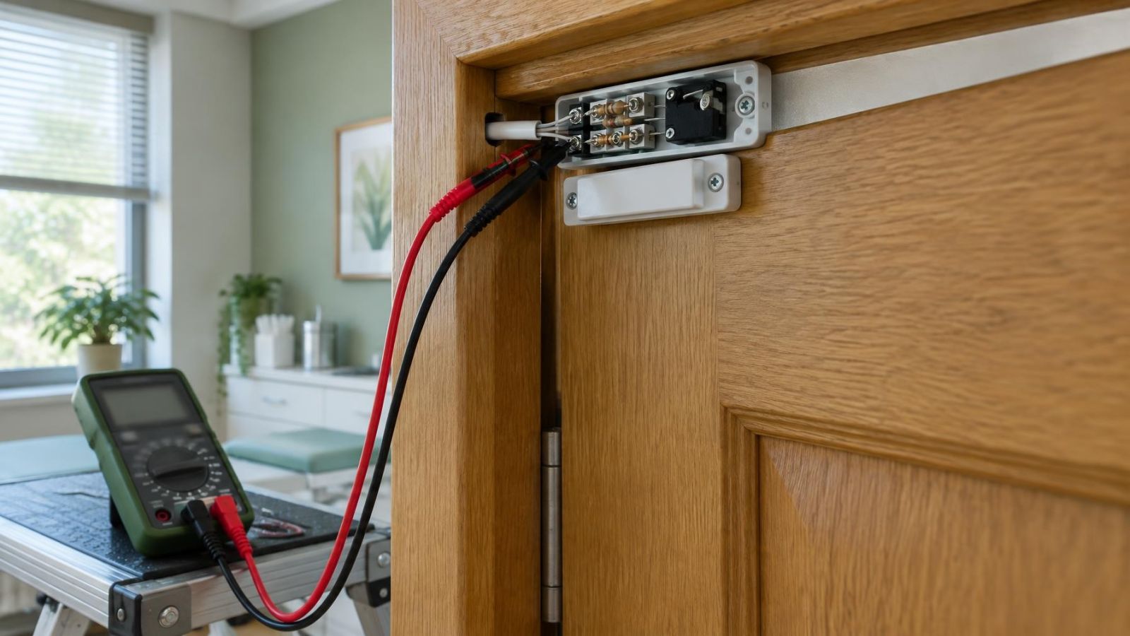
The resistor must be at the electrically monitored end of the cable, normally inside the detector enclosure or the final protected junction. If it is fitted across the zone terminals inside the control panel, the panel can confirm the resistor but not the outgoing field cable. A cut, disconnection or short beyond those terminals may then go unnoticed or be misinterpreted.
Some circuits use one resistor and distinguish a limited set of states. Others use additional resistive paths through detector and tamper contacts. More states can provide more diagnostic information, but only when the panel input supports the arrangement and has been configured to interpret it correctly.
Open, Short, Alarm, and Tamper States
The words shown by a keypad, application or monitoring interface are interpretations of electrical readings. An open condition may come from a detector contact, a removed cover, a disconnected terminal or damaged cable. A short may come from crossed conductors, trapped insulation or a bridge across the loop. The displayed description depends on the zone configuration.
| State | Possible electrical condition | What it may represent |
|---|---|---|
| Normal | Expected resistance range | Intact loop with detector at rest |
| Alarm | Configured change in resistance or contact path | Detector activation |
| Open | Very high resistance or no continuity | Opened contact, loose terminal or broken cable |
| Short | Very low resistance | Crossed conductors, cable damage or bypassed path |
| Tamper | Separate input or configured resistance state | Opened enclosure or disturbed tamper path |
These are functional categories, not universal resistance values. A reading treated as an alarm by one wiring design could be treated as a fault by another. Changing resistor values, moving conductors or replacing a detector without checking the zone design can therefore change the meaning of every state.
How Does an Alarm Tamper Circuit Fit In?
A tamper switch usually changes state when a detector or junction enclosure is opened. It may connect to a separate tamper circuit, giving the panel an independent indication, or share the supervised zone loop through a designed resistance path. Shared monitoring uses fewer field conductors but requires the wiring and panel interpretation to match exactly.
Not every shared loop provides a separately labelled tamper state. Some configurations show tamper activity as a general fault, an open circuit or another zone condition. The practical question is not only whether a tamper switch exists, but whether the complete circuit lets the panel distinguish it from detector activation and cable damage.
How Are Wiring Faults Diagnosed?
Diagnosis starts at the control panel. Note the affected zone, the reported state and whether the indication is constant or intermittent. Then identify every device, joint and cable section belonging to that zone. In an apartment, a route may pass through shutter boxes or concealed junctions. In a private home or street-front business, it may continue outdoors to a gate, garden detector or external door contact.
- Record the panel indication before resetting or moving any conductors. A changing display can be useful evidence about an intermittent connection.
- Inspect accessible terminals, detector covers and junction points. Look for loose strands, damaged insulation, strained cable and signs of moisture or dust.
- Isolate the relevant circuit using the correct procedure for the installed panel. Resistance and continuity measurements should not be made on an energised loop.
- Measure the complete field loop at the panel end and compare the result with the intended normal state. A reading alone is not meaningful without the expected circuit arrangement.
- Disconnect and test sections of the loop to divide the route. Moving the test point towards the field devices narrows the section containing the unexpected resistance.
- Reconnect each termination carefully, then verify normal, detector activation, fault and tamper behaviour at the panel where the circuit supports those distinct states.
A multimeter confirms electrical conditions; it does not explain them automatically. An open reading could indicate a broken conductor, an opened contact or a lead removed for testing. An unexpected resistance may come from a poor joint, the wrong resistor, parallel devices or contamination across a termination.
Dividing the circuit is usually more reliable than repeatedly resetting the panel. A supervised zone can report that its expected condition has disappeared, but it does not know whether the problem is beside the panel, above a door, inside a shutter box or at an outdoor detector. Physical testing supplies the missing location.
Plan Supervision at the Detector
Good supervision begins with resistor placement. The component belongs at the true end of the monitored field wiring. On a zone with several devices, that means understanding the complete electrical route rather than placing the resistor at whichever detector is physically closest to the panel.
Terminations should remain accessible for inspection while being protected from casual disturbance, dust and moisture. Hiding a resistor inside an undocumented wall joint may leave the circuit electrically correct but unnecessarily difficult to maintain. At a shared apartment-building entrance, the zone route may also pass through common service spaces, so identifying the relevant panel and field wiring before work begins is particularly important.
Documentation need not be elaborate. It should state the zone purpose, cable route where known, conductor use, device order, resistor location and whether tamper monitoring is separate or combined. Labels should match the panel description closely enough that a remote owner, business manager or another installer can identify the same circuit without guessing.
- Place the resistor beyond the field cable section that needs supervision.
- Use protected, serviceable detector or junction terminals.
- Record conductor colours by function rather than relying on colour alone.
- Document all devices sharing the loop and the order in which the cable reaches them.
- Confirm which electrical states the panel is configured to interpret as normal, alarm, fault and tamper.
Where the equipment supports it, keeping alarm and fault interpretation distinct makes operation clearer. A detector event then communicates something different from a broken cable or disturbed enclosure. That distinction is created by the whole design: contacts, resistors, cable paths, tamper switches and control-panel configuration must agree.
Existing wiring should be reviewed before resistors are moved or detector connections are altered. A circuit that looks unconventional may serve several devices or use a shared tamper path. Changing one termination without mapping the loop can remove supervision from another section or turn a valid detector state into a persistent fault.
Key takeaways
- Loop resistance gives a control panel more information than a simple open-or-closed detector contact.
- An end-of-line resistor belongs at the monitored end of the field cable, not beside the control panel.
- Fault detection depends on both the physical wiring arrangement and the control panel configuration.
- A panel indication can narrow the diagnosis without identifying where the cable is damaged.
- Clear records of conductors, joints and resistor locations make later fault finding faster and less ambiguous.