On this page
An unfamiliar property may contain security cameras, a video recorder, an alarm control panel, wired detectors, more than one power supply and network cabling that disappears into walls without labels. Before replacing equipment, you need to map the undocumented security system well enough to know what connects to what, which findings are verified and which routes remain uncertain.
This is not simply a camera list. A reliable map links every visible device to its cable, power source and connected equipment. It also records physical condition, location, intended purpose and any dependency that could affect the upgrade. Done properly, the survey prevents a new design from being based on untested assumptions.
Start With an Equipment Inventory
Begin with what can be seen. Walk through the property without disconnecting anything. Record every security camera, alarm detector, keypad, siren and door contact. Include equipment that appears unused. A disconnected device may still have a serviceable cable, while a device that looks active may no longer be connected to the main system.
Then locate the central equipment. This may include an NVR (network video recorder), DVR, alarm control panel, network switch, router, power distribution unit and backup power equipment. Some systems are concentrated in one cabinet. Others have grown in stages and may be spread between a service cupboard, office, ceiling void and communications enclosure.
- Give each item a temporary identifier and record its exact location.
- Photograph the device in context, then photograph its connectors, cable entry and visible label.
- Note visible cable types, including network cable, coaxial cable and multi-core alarm cable.
- Record cracked housings, corrosion, loose connectors, damaged insulation, blocked vents and improvised joints.
- Mark equipment as active, apparently inactive or unknown without guessing from appearance alone.
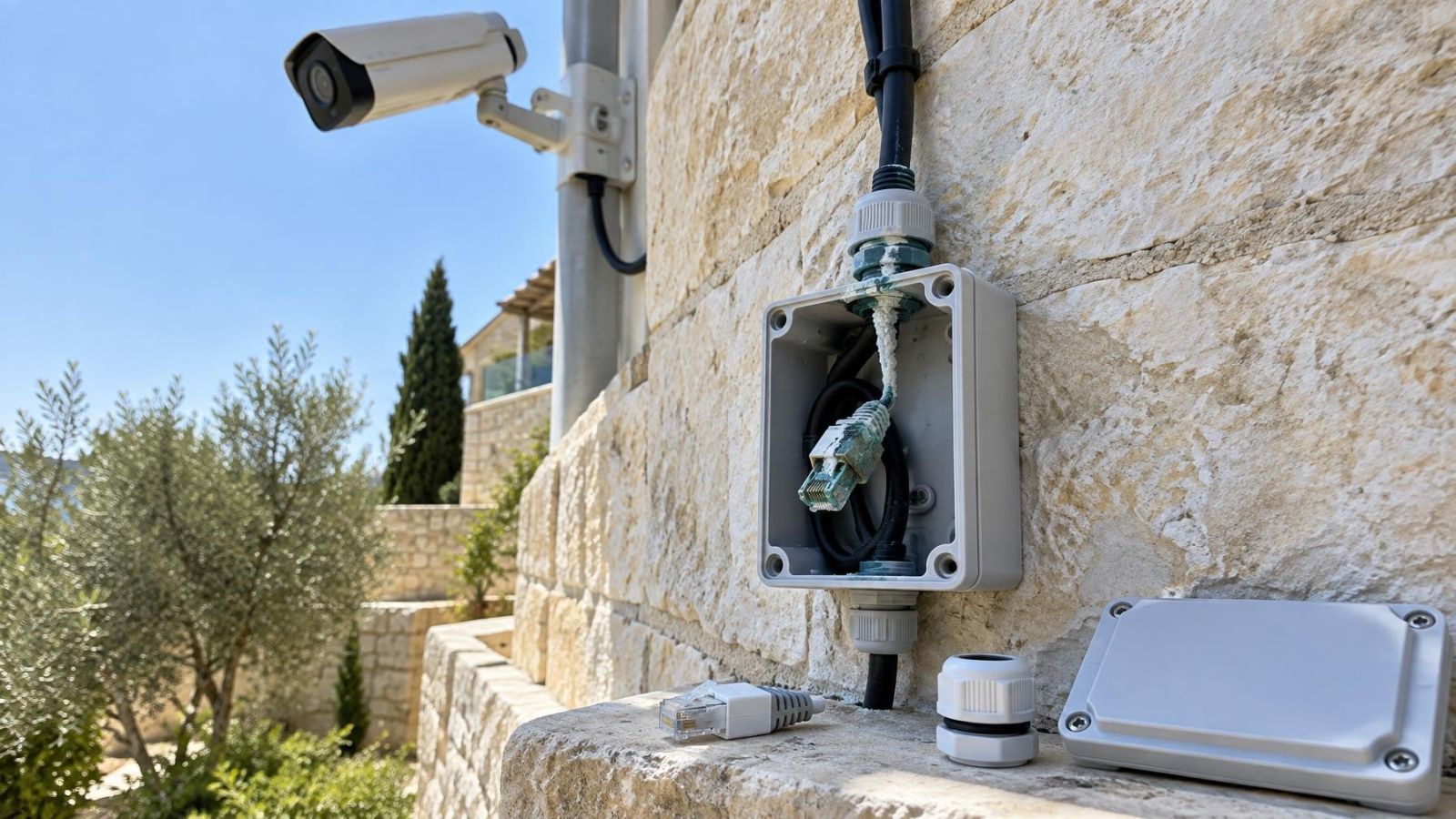
Israeli properties can expose equipment to strong sunlight, dust, garden irrigation and coastal humidity. Check outdoor junction boxes and cable entries carefully. Faded plastic is not by itself proof of failure, but moisture marks, brittle insulation and corroded terminations need further investigation.
What should an existing security system map show?
An existing security system map should show each device, its identifier, location, cable, power source and connection to central equipment. It should also distinguish verified information from assumptions. A clean-looking drawing is less useful than an honest one that marks an inaccessible conduit or unknown junction as unconfirmed.
Build a Room-by-Room Point Plan
Use a floor plan if one exists. A simple sketch is enough when it does not. Divide the property into rooms and external areas, then mark every device point. Use a consistent naming method such as area plus device type. The identifier should remain short enough to fit on a cable label and specific enough that two similar devices cannot be confused.
For each security camera, mark its position and viewing direction. Record what the view is meant to cover: an entrance, gate, garden path, stock area, till position or street-facing frontage. Do not assume the current angle is the intended one. Plants, signs, shelving and changes to the building may have altered the useful field of view.
For alarm equipment, record the detector location and the zone shown at the keypad or panel, if it can be confirmed. Detectors may share an enclosure or cable route while belonging to different zones. Keep physical cable grouping separate from logical zone assignment.
- Separate indoor, outdoor and shared-building areas on the plan.
- Mark gates, garden structures, parking access and street frontage as distinct locations.
- Include the mamad, commonly called the safe room in English, rather than treating it as an ordinary unnamed room.
- Show shared entrances, stairwells and service cupboards separately from the private apartment or business unit.
- Add inaccessible spaces, concealed ceilings and locked enclosures even when their contents are unknown.
In an apartment building, establish where the private system ends and shared infrastructure begins. A cable may leave the apartment and pass through a common communications area. Record that boundary without assuming that equipment in a shared cabinet belongs to the property being surveyed.
Where Do the Cables Converge?
Camera cables usually converge at a recorder, network switch, patch panel or power cabinet, but not always at the same place. Analogue video may reach a DVR while camera power comes from a separate supply. An IP security camera may connect to a PoE (power over Ethernet) switch, which then connects to the recorder through another part of the network.
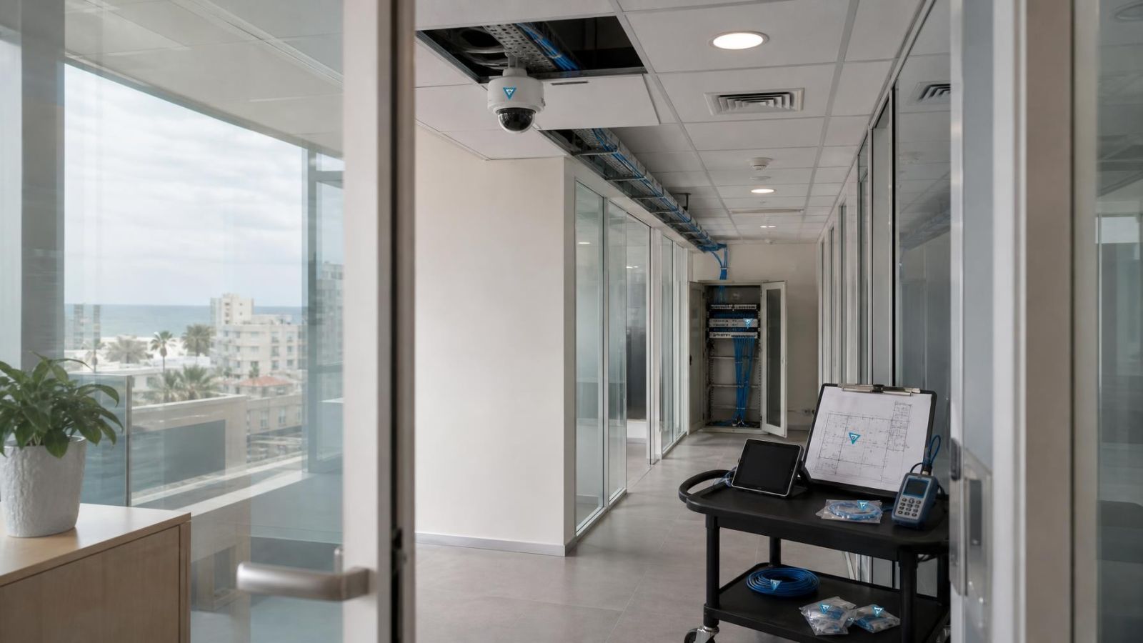
Alarm cables normally return towards the alarm control panel or an intermediate expander enclosure. Follow visible cable bundles through service cupboards, ceiling voids and accessible conduits. Look for changes in cable colour, diameter or labelling that suggest a splice or intermediate connection.
- Record the recorder and alarm-panel locations separately, even if they occupy the same cabinet.
- Identify network enclosures, patch panels and switches that sit between cameras and the recorder.
- Mark power cabinets and backup power equipment as independent dependencies.
- Note conduits or cable bundles that continue into another floor, unit or shared service area.
- Treat every route hidden inside a wall, ceiling or conduit as unconfirmed until traced or tested.
How Do You Trace CCTV Cables?
Start with non-destructive visual tracing. Follow each cable as far as access allows and compare its type, colour, printed markings and route at both ends. Photograph every point where the cable disappears. Visual similarity is supporting evidence, not proof: several cables from the same installation can look identical.
When operational conditions allow, disconnect one circuit at a time using a controlled process. Record the starting state, isolate the selected cable from connected electronics, test it, label it and reconnect it before moving to the next circuit. Avoid opening or disturbing unknown mains wiring. Power supplies can contain both mains and low-voltage connections even when the outgoing device cable appears harmless.
- Choose one device and assign its permanent identifier.
- Record the ports, terminals and displayed status before touching any connection.
- Isolate only the relevant cable from connected equipment.
- Use the suitable test method for that cable type.
- Confirm the far end and apply the same identifier at the device end, central end and floor plan.
- Reconnect the circuit and verify that the documented equipment returns to its previous operating state.
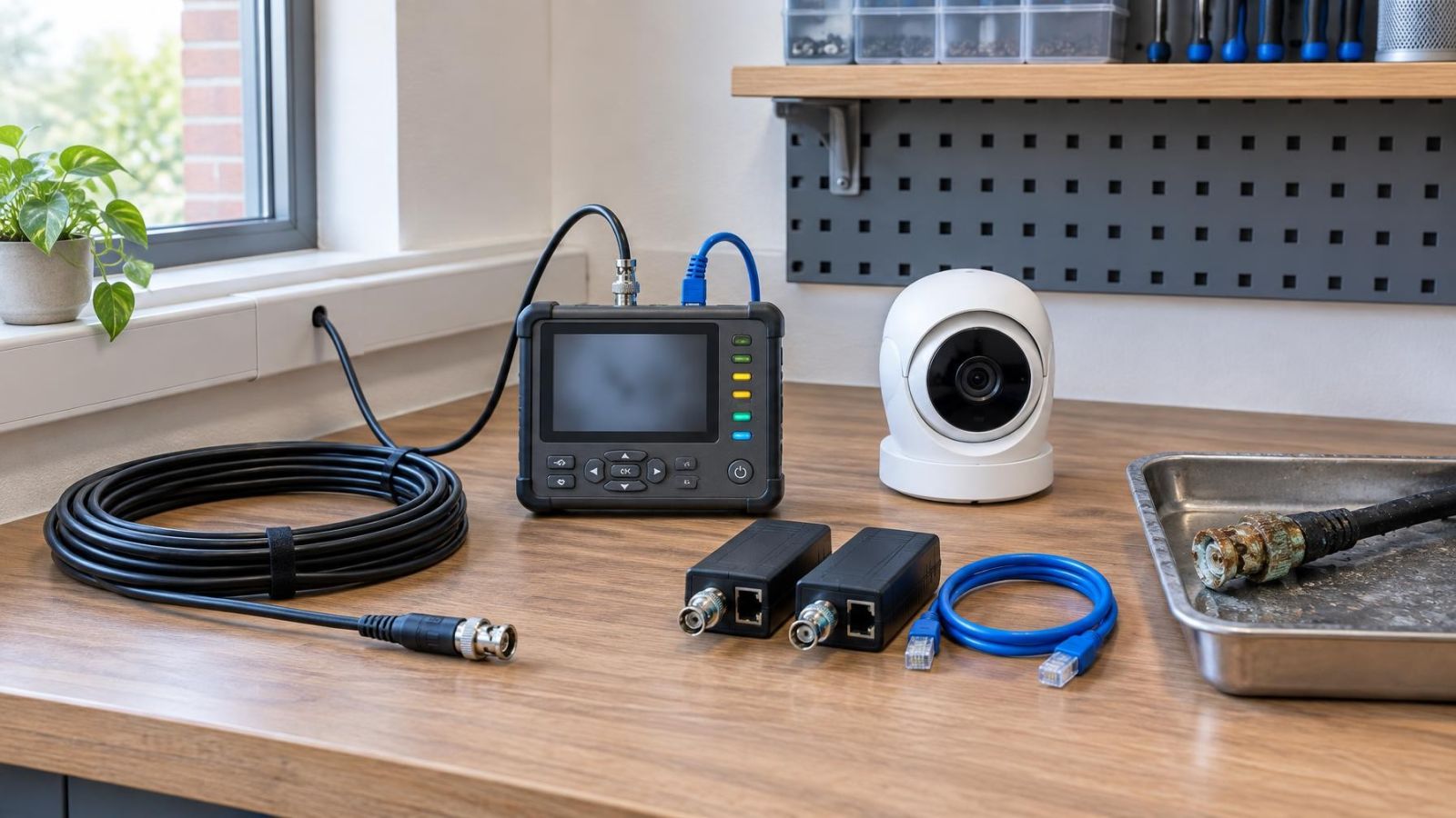
Continuity testing can confirm a conductor path after the cable is safely disconnected from electronics. A cable toner can help follow compatible wiring through accessible bundles. A network cable tester can identify conductor order and basic termination faults. Coaxial cable requires methods and adapters suited to coax rather than network cabling. No single tester proves the condition of every cable type or confirms the entire concealed route.
How Do You Identify Camera Cables?
Identify camera cables by combining endpoint inspection, controlled disconnection and appropriate testing. For an IP system, match the camera to its switch port and recorder channel rather than relying only on cable colour. For an undocumented CCTV system using coaxial cable, trace both the video path and the power path because they may terminate in different cabinets.
A temporary observation such as “camera went offline when this port was disconnected” is not a finished label. Confirm the result, restore the connection and apply the identifier at all relevant points. If a route disappears into an inaccessible conduit, document the known endpoints but mark the route between them as unconfirmed.
Record Power and Network Dependencies
The visible cable behind a security camera may not tell the whole story. Power, video transport and network access can follow different paths. A camera may receive local power near the device while sending video over coaxial cable. Another may receive both data and power from a central PoE switch. A third may connect through an intermediate switch hidden above a ceiling.
Draw dependencies as connections rather than as a flat equipment list. Show which cameras depend on each switch, which switch connects to the router or recorder, and which power supply serves each group. If the recorder depends on network equipment in another room, that relationship belongs on the map.
- Record whether each camera uses local power, central power or PoE.
- Identify devices sharing a power supply or backup power source.
- Show the relationship between recorder, switches, router and any VMS (video management software) host.
- List alarm-panel terminals, detector zones and shared cable routes separately.
- Mark unknown splices, junction boxes and intermediate network connections for investigation.
A shared power supply creates a shared point of interruption. The same applies to an intermediate switch. This does not automatically mean the arrangement must be replaced, but it must be visible in the plan so that upgrade work does not remove a dependency that other equipment still uses.
Remote property owners should ask for evidence that can be checked without being on site: labelled overview photographs, close-ups of terminations, a floor plan and an equipment schedule using the same identifiers. A collection of unlabelled photographs rarely provides enough context to make a reliable decision.
Assess What Can Be Reused
Existing cabling can be reused only after its type, condition, terminations and intended function are understood. Age or appearance alone does not settle the question. A clean cable can have poor concealed joints, while an older route may remain useful after damaged terminations are corrected. Testing should come before any compatibility assumption.
Inspect the complete accessible path. Check cable jackets at outdoor entries, tight bends, unsupported sections and places where cables pass near doors or cabinet edges. Examine connectors for corrosion, looseness and poor termination. Near the coast, connection condition deserves particular attention even when the equipment is indoors.
- Confirm that the cable type suits the proposed signal and power method.
- Test conductor continuity and termination quality using methods appropriate to the cable.
- Check whether the route can remain accessible for future maintenance.
- Verify that power delivery is suitable for the intended equipment and route.
- Confirm that the network path supports the proposed connection arrangement.
- Reassess camera position, sunlight, glare and night vision rather than reusing a location automatically.
A technically reusable cable may still follow the wrong route or finish at an unsuitable position. For example, a camera mounted towards an Israeli street frontage may face intense backlighting for part of the day. WDR (wide dynamic range) can help a camera manage contrasting light, but it does not correct a poor mounting angle, obstructed view or direct glare on the lens.
Turn the Map Into an Upgrade Plan
Convert each surveyed item into one of three working decisions: keep, replace or investigate. Keep means the item or route has been verified for the proposed use. Replace means its condition, position or function does not suit the plan. Investigate means the available evidence is incomplete. It should not be treated as a softer version of keep.
List priority faults separately from documentation gaps. A damaged outdoor connector is a fault. An inaccessible conduit is a gap in knowledge. Both affect the scope, but they require different work. Also note any active device that cannot be interrupted during ordinary business hours or while occupants depend on it.
- Replace temporary survey tags with durable final cable and device labels.
- Use the same identifier at the device, both accessible cable ends, the floor plan and the equipment schedule.
- Update camera directions, alarm zones, switch ports, recorder inputs and power-supply relationships.
- Retain notes for unconfirmed routes, inaccessible areas and assumptions that still require testing.
- Define installation work by location and identifier rather than by vague descriptions such as rear camera or old cable.
The finished package should include an updated floor plan, equipment schedule, cable record, dependency diagram and list of unresolved questions. It should be possible for another installer to enter the property, find a device and follow its documentation without first reconstructing the survey.
A useful system map does not hide uncertainty. It shows what has been verified, what has been assumed and what remains inaccessible.
That distinction is what turns a security system audit into a practical upgrade plan. New equipment can then be selected around known routes and dependencies, while uncertain infrastructure is given a clear investigation task rather than being accepted by default.
Key takeaways
- Every device should be inventoried before cables are disconnected or tested.
- Matching identifiers at the device, cable end and floor plan make future maintenance substantially clearer.
- Verified cable routes must be documented separately from assumptions and inaccessible sections.
- Existing infrastructure should be tested before any decision is made to reuse it.
- Survey findings become actionable when each item is marked keep, replace or investigate.