On this page
An alarm control panel sits between sensor inputs and programmable outputs. A relay module may operate connected equipment, a siren may produce an alarm sound, and a notification pathway may alert someone elsewhere. These input and output devices are easy to connect but easy to configure badly when the intended response is unclear. The question to settle before programming is simple: when each event occurs, what should the equipment do, what should a person do, and how should the system return to normal?
Separate input and output devices
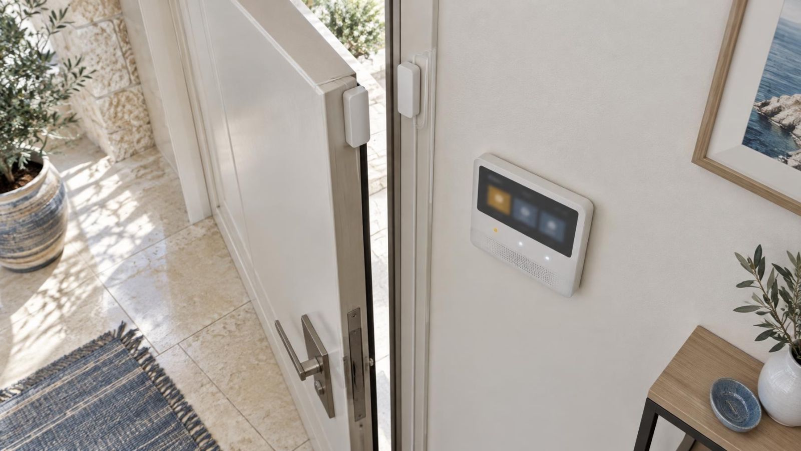
An input reports an event or condition to the control panel. Door contacts, movement sensors, panic buttons and equipment fault contacts are all event sources. Depending on the device, an input may report that a contact opened, closed, remained active or returned to its normal state. It does not decide the overall response.
An output acts because the panel logic tells it to act. Sirens, strobe lights, notification pathways and programmable relays are common examples. An output does not detect the original event. It receives a command based on the input, the arming state, timing rules and other programmed conditions.
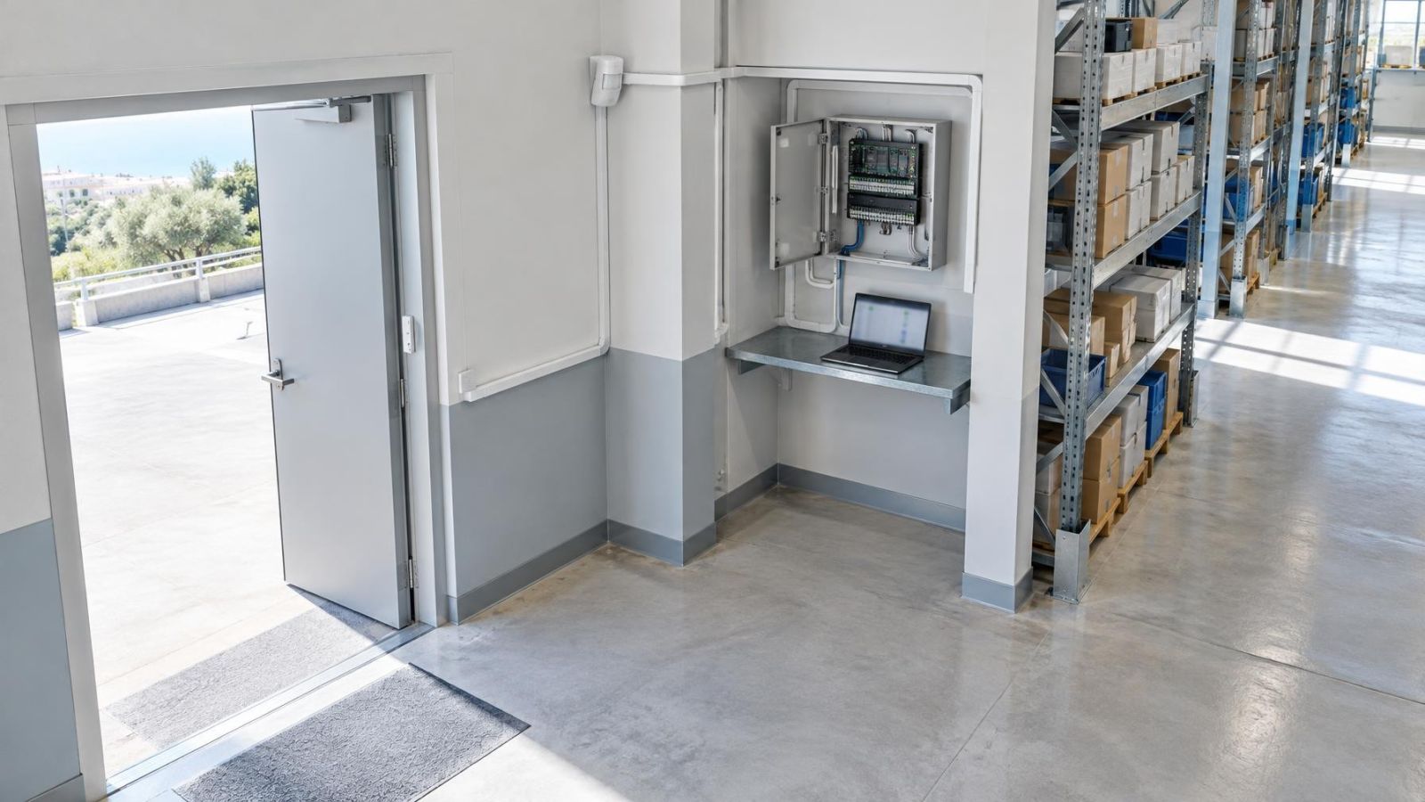
The control panel is the decision point. It interprets the event, checks the current system state and applies the programmed response. Keeping these roles separate makes the design easier to review. It also prevents vague requirements such as “connect the gate to the alarm” from reaching the programming stage without defining whether the gate is an event source, controlled equipment or both.
Clear names matter from the beginning. “Zone 4” says little during a test or fault. “Shop rear stockroom door” or “House garden gate contact” identifies the location and the device. Output names should be equally direct, such as “Internal siren”, “Gate release relay” or “Manager fault notification”. Good names make daily use, testing and later maintenance much easier.
What should each event cause?
Define the response before opening the programming menus. Start with the event and write down the required local action, remote action, relay behaviour and human action. Programming then becomes an implementation task rather than a series of guesses made at the panel.
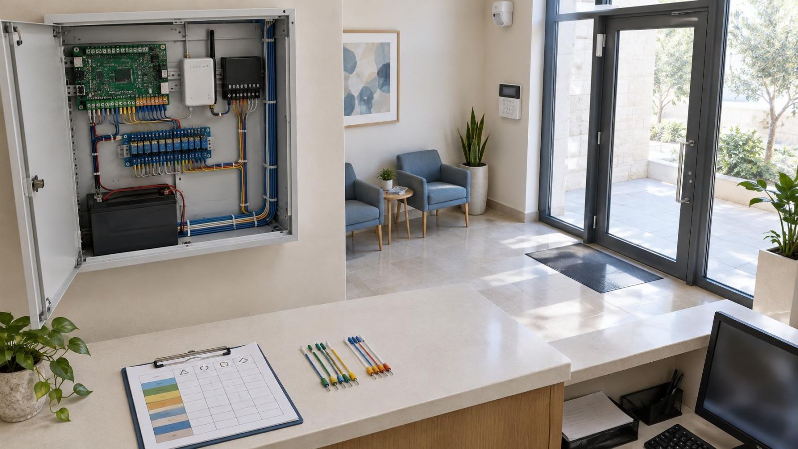
An input-to-output response matrix is the clearest working document. Each row represents one event in one relevant state. The columns show everything expected to happen. Include “no action” where silence or inactivity is deliberate; a blank cell can be mistaken for an unfinished decision.
| Event and condition | System state | Local response | Remote or relay response | Expected human action |
|---|---|---|---|---|
| Entrance contact opens | Armed, after entry delay | Configured audible response | Alarm notification | Verify the event and follow the agreed procedure |
| Entrance contact opens | Disarmed | Optional indication only | No action | Close the entrance if appropriate |
| Sensor reports a fault | Any relevant state | Fault indication | Maintenance notification | Inspect or arrange service |
| Input returns to normal | After an active event | Restore indication | Restored notification if required | Confirm whether a manual reset remains necessary |
Alarm events and fault events should not share an undefined response. An alarm event reports the condition the system was designed to detect. A fault condition reports that part of the system may be unavailable, disconnected or unable to communicate. Both need a planned destination, but they may need different sounds, messages, recipients and reset procedures.
The final column of the matrix is often the most useful: what should the recipient do? A message that identifies a device but leaves the user uncertain about the next step is incomplete. The expected action might be to inspect a door, acknowledge a fault, contact a responsible person, or wait for an authorised reset. The correct action depends on the site and its operating procedure.
How should a fire alarm system fit the plan?
The same cause-and-effect discipline applies: define each event, state, output and human response before configuration. However, life-safety functions should not be treated as convenient spare inputs or relays for unrelated automation. Preserve the intended alarm, fault, acknowledgement and reset paths. Testing should be performed by people who understand the complete system and the equipment connected to it.
Account for system state
The same sensor input can require different responses according to the system state. An entrance contact opening while the premises are occupied and disarmed may need only a local indication. The same contact opening while the relevant area is armed may start an entry delay or an immediate response, depending on its purpose.
Write down armed and disarmed behaviour separately. Do not assume that disarmed means inactive. Panic functions, equipment faults, environmental sensors and other continuously monitored inputs may remain active regardless of the intrusion arming state. Conversely, some convenience notifications may be useful only while people are present.
Entry and exit delays also need explicit logic. Identify which input starts the delay, which actions occur during it, what cancels it, and what happens when it expires. A quiet keypad indication, a local warning tone and a full alarm response are different outputs and should not be described with one vague label.
Compare occupied and unoccupied operation. During occupied periods, an internal siren or strobe light may be useful for immediate awareness, while certain automation actions could be disruptive. During unoccupied periods, remote notification may carry more importance. This is not a universal rule; it is a prompt to make the decision deliberately.
Shared entrances and gates need special care because several people may operate them and the alarm system may not control the shared equipment. Decide whether the system monitors the entrance, controls it, or only receives a status contact. Also define what happens when a gate remains open, closes during an exit delay or is opened by someone who does not use the alarm panel.
Which conditions change the response?
An input is more than “normal” or “alarm”. The panel may be able to distinguish an opening transition, a closing transition, a persistent active state and a restoration. Decide which transition matters. A door opening may start a response, while its later closure may simply create a log entry. Another application may require a notification when the door is restored.
Duration matters too. A brief activation may come from normal movement, contact bounce or a short operating cycle. A persistent activation may indicate that a door was left open or that a device remains in an active condition. If duration changes the response, define the threshold within the panel’s supported logic and test both sides of it rather than assuming the setting behaves as its label suggests.
Plan for loss of power and communication as events in their own right. Decide which failures should appear locally, which should travel through an available notification pathway, and what should happen when service returns. A communication failure cannot be reported through the same failed path, so the matrix should not claim a response that the system cannot deliver.
Repeated or multiple alarm events also need boundaries. Without a plan, users may receive a stream of identical messages that adds no useful information. Decide whether repeated events are logged, grouped, silenced after acknowledgement or escalated to another recipient. Escalation should have a defined purpose and an end condition, not an endless cycle.
A response plan is complete only when it covers activation, persistence, restoration, fault and reset.
Design relay actions carefully
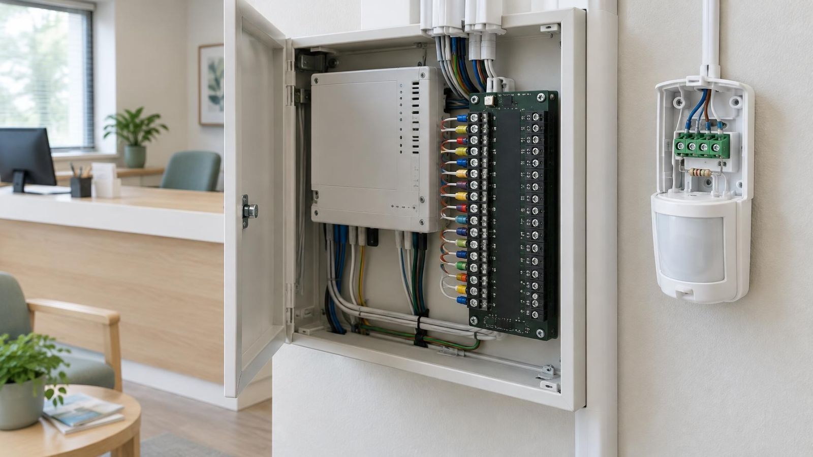
A relay output changes an electrical contact in response to panel logic. A dry contact normally does not supply operating power to the connected equipment. It acts more like an electrically controlled switch. The lock, gate controller, light interface or other equipment may need its own suitable power source and interface.
Choose between momentary and maintained behaviour deliberately. A momentary output changes state for a defined period and then returns. It may suit equipment that expects a short command. A maintained output remains changed until another event, reset or manual action releases it. Using the wrong behaviour can cause repeated operation or leave equipment in an unintended state.
The safe default state must be considered for normal operation, loss of panel power, cable damage and module failure. “Normally open” and “normally closed” describe contact state, not whether the connected equipment is safe or appropriate. Review what the connected device does when the relay is idle, active, unpowered and disconnected.
Check the electrical limits of the relay and the requirements of the connected equipment. Contact type, switching load, voltage type, current demand and any inductive load all affect the interface. If the load exceeds what the panel output can handle, use a suitable interface rather than driving the equipment directly.
Every controlled action needs a manual override and a reset path. State who can use the override, how the panel shows that an override is active, and whether normal logic resumes automatically. A hidden override that leaves automation disabled is difficult to diagnose later.
Test complete response scenarios
Testing an input and hearing a panel beep does not prove the full response. The test must follow the complete path: physical activation, input recognition, panel decision, output operation, remote delivery, event logging and restoration. If any link is skipped, the response plan remains partly unverified.
- Place the system in the state named in the response matrix, including the correct armed area, occupancy condition and delay mode.
- Activate the real sensor or contact where practical, rather than changing only a software value at the panel.
- Observe every intended audible, visual, relay and remote response, including its timing and duration.
- Perform the expected acknowledgement, override or reset action and confirm that outputs return to their planned state.
- Review the event log for clear device names, correct event order and accurate restoration or fault entries.
- Repeat the scenario under the other relevant states and simulate credible power, communication and device faults.
Normal-use tests are as important as alarm tests. Walk through ordinary entry and exit, opening a shared gate, disarming after an entry delay, acknowledging a fault and restoring a disconnected device. These scenarios reveal nuisance sounds, confusing messages and relay actions that isolated bench tests may miss.
Confirm responses through more than one sense and location where the design calls for them. Listen for the intended audible indication, view panel or strobe status, check connected equipment and verify remote messages. The event log should show the same sequence that the people testing observed.
Before handover, the people who will use the system should accept the practical behaviour, not merely the programming list. They should understand the messages, delays, reset procedure and manual controls. If the behaviour is technically correct but confusing in normal use, revise the plan and test it again.
Document the final response plan
Keep the approved response matrix with the system records. Use the same plain-language input and output names in the matrix, control panel, notifications and equipment labels. Consistent naming reduces the chance that a later technician will test one device while reading instructions for another.
The record should include each event, relevant system state, delay, local output, remote action, relay behaviour, expected user action and restoration method. Add reset and override instructions in language the everyday users understand. Technical relay details can sit beside those instructions without replacing them.
Record later programming changes as changes to the response plan, not only as altered panel settings. Note what behaviour was intended, which matrix rows were affected and which complete scenarios were retested. Otherwise, the documented design and the working configuration gradually separate.
The final decision should always precede configuration: agree what people and equipment are meant to do, approve the matrix, then program the panel to match it. This order produces a system that can be explained, tested and maintained without relying on the memory of whoever programmed it.
Key takeaways
- Define the required response before assigning any sensor input or programmable output.
- Every relevant event should map to a clear audible, visible, remote or relay action, including an intentional decision to take no action.
- System state, fault conditions, delays and reset behaviour can change how the control panel responds to the same input.
- Complete testing follows the event from the sensor through the control panel to every local and remote response.
- The approved response matrix should remain with the system records and be updated after every programming change.