On this page
A CCTV camera may start normally on a camera power supply, then restart, lose its image or switch off when its infrared illuminator activates. A multimeter can show whether the fault begins in the supply, the power cable, a connector or the camera itself. The important point is to test while current is flowing, not only with the camera disconnected. This guide explains how to perform that load test and interpret the readings.
Recognise a CCTV camera power fault under load
A supply can produce the expected voltage when nothing is connected yet become unstable as soon as the camera draws current. An unloaded reading confirms only that some voltage is present. It does not confirm that the adapter can maintain that voltage in normal operation.
Repeated restarting is a common load-related symptom. The camera begins to boot, its demand rises, the voltage falls, and the camera resets. Demand may also increase when the infrared illuminator switches on, when an internal heater operates, or when another powered function becomes active. The image may disappear only at night or during startup even though the camera works at other times.
- The adapter reads normally with the camera disconnected but falls noticeably when it is connected.
- The camera restarts or loses video when its infrared illuminator activates.
- The image fails during startup or another period of peak current draw.
- A plug, socket or terminal feels unusually warm after the power has been isolated, or shows discolouration, looseness or corrosion.
- Several cameras on a shared electrical supply show similar symptoms when more outputs are in use.
Similar behaviour can have other causes. A network fault can interrupt viewing while the camera remains powered. A recorder can stop displaying a channel even though the local camera is operating. Before treating image loss as a power problem, check whether the camera actually restarts, whether status indicators go out, or whether its infrared illuminator repeatedly switches.
What should you test first?
Begin with compatibility and condition before taking live measurements. Read the camera label and supply label. Confirm the required DC voltage, connector type and polarity. The supply voltage must match the camera requirement. Its available current must be sufficient for the camera's highest operating demand. A higher available current rating is not the same as forcing extra current into the camera; the camera draws what it needs.
Polarity matters. A connector that fits physically may still have its positive and negative conductors reversed. Incorrect polarity can prevent operation or damage the camera. Do not substitute a supply until voltage, polarity and connector arrangement are known to be compatible.
- Inspect the full visible length of the power cable for crushing, cuts, sharp bends and strained joints.
- Check plugs and sockets for looseness, bent contacts, dirt, moisture, corrosion and heat marks.
- Confirm that screw terminals grip clean conductor rather than insulation.
- Try a short known-good power lead where the layout permits.
- Disconnect shared loads temporarily so one camera and one supply output can be assessed at a time.
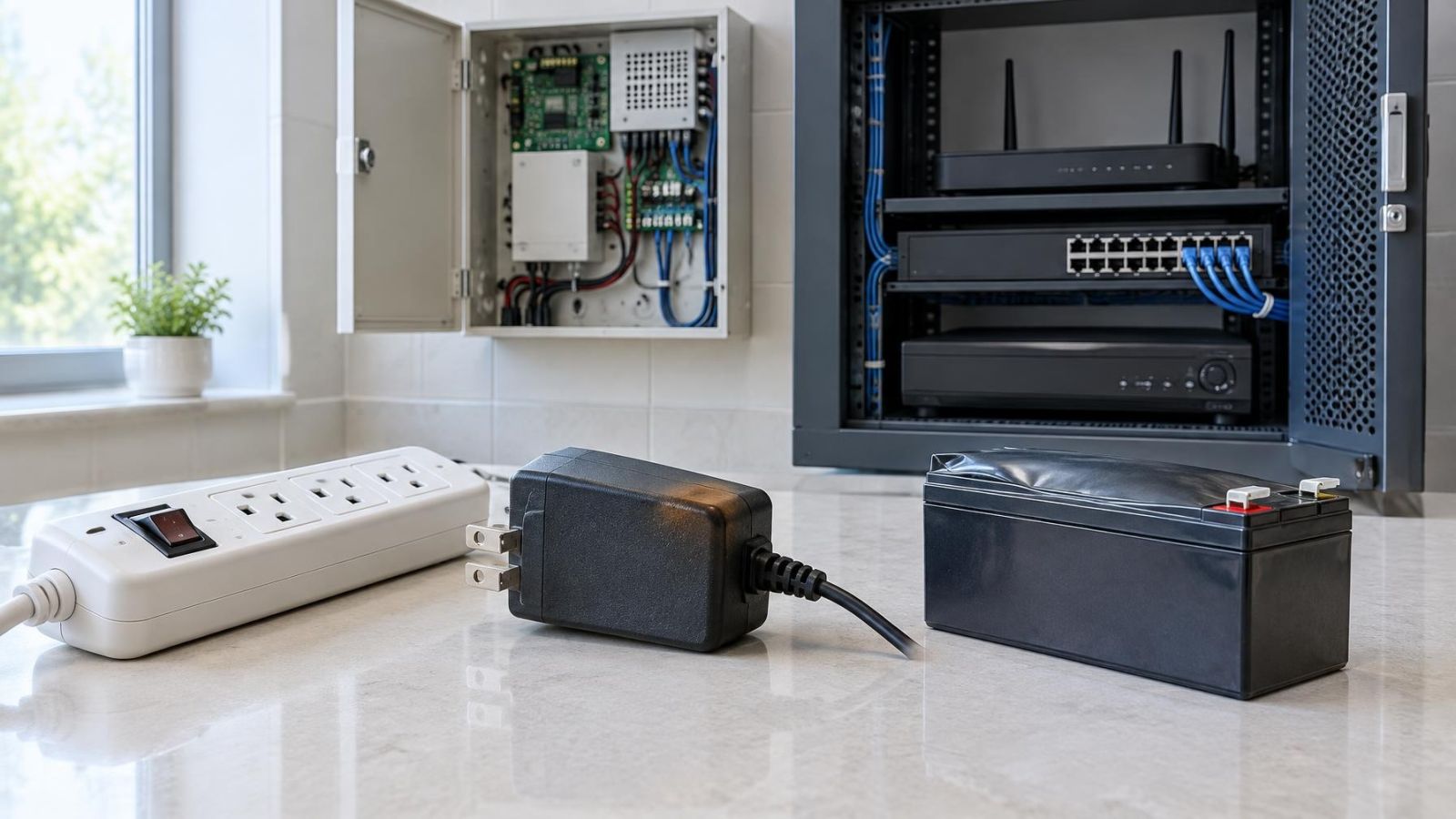
A dedicated adapter is easier to separate from the camera than a shared power unit. With a shared unit, identify the correct output and record which other cameras are connected. For a WiFi camera, do not assume a wireless network connection means wireless power: the adapter, low-voltage cable and input connector still need the same checks.
Prepare the test safely
Keep the test on the isolated low-voltage DC side. Unplug mains-powered equipment before exposing, moving or reconnecting conductors. Do not open an adapter or shared power enclosure to reach mains-side parts. If access to the low-voltage output requires working near exposed mains connections, stop and use a competent technician.
Set the multimeter to DC voltage and choose a range suitable for the labelled output. Put the black lead in the common terminal and the red lead in the voltage terminal. Inspect the probes and insulation before use. Fine probe tips or suitable test clips are preferable to forcing oversized probes into a small connector.
- Arrange the camera and cable so nothing can pull a live connector apart during testing.
- Keep probe tips from touching each other or bridging adjacent terminal screws.
- Cover exposed conductor that is not part of the measurement.
- Support the connector instead of twisting it to obtain a reading.
- Switch off power before changing wiring or moving a probe between terminal positions.
Voltage is measured across two points while the circuit remains connected. Current is measured by opening the circuit and placing the meter in series. Confusing these methods can create a direct short through the meter. Leave current testing until later, and do not attempt it unless you understand the meter terminals, range and fuse arrangement.
Test voltage under real load
Use the same measurement points throughout so the results can be compared. Note the polarity shown by the meter. A negative sign usually means the probes are reversed, but confirm the actual connector polarity rather than simply swapping assumptions.
- Disconnect the camera and measure the adapter output with no load. Compare the reading with the labelled output, but do not treat a normal result as proof that the supply is healthy.
- Switch off power, reconnect the camera, arrange safe access to the low-voltage conductors, and restore power.
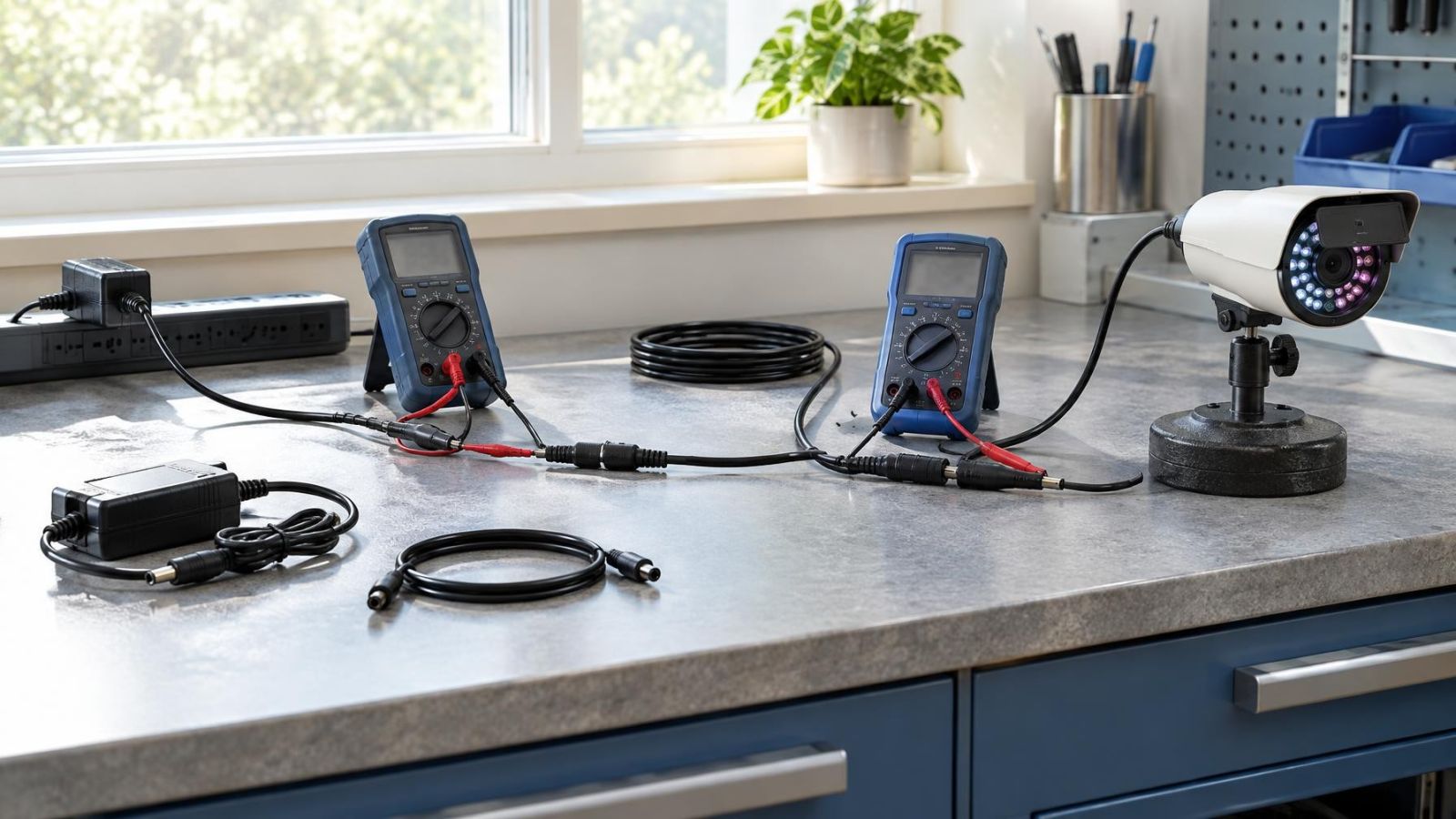
- Measure at the supply output while the camera is operating. Watch the reading during initial startup rather than checking only after the image appears.
- Measure at the camera input without disconnecting the load. This is the voltage the camera actually receives.
- Cause the camera to enter each normal operating mode available to you. In particular, observe the reading as the infrared illuminator switches on and off.
- Repeat any suspicious transition. A brief dip may be easier to identify with a meter that can capture minimum voltage, but a basic display may still reveal repeated collapse or fluctuation.
The comparison between the two ends is more useful than either reading alone. If voltage falls at the supply output, the adapter or shared supply is struggling with the load. If the supply output stays stable but the camera input is lower, resistance in the cable, joints or connectors is consuming part of the voltage.
| Supply-end reading | Camera-end reading | Likely area to investigate |
|---|---|---|
| Stable under load | Stable and similar | Look beyond basic power delivery, including the camera and video path |
| Falls under load | Falls with it | Adapter capacity, shared supply loading or abnormal camera current draw |
| Stable under load | Lower or unstable | Power cable, joints, plug, socket or terminal resistance |
| Stable with one camera but falls with several | Affected cameras become unstable | Shared supply capacity, distribution wiring or one abnormal branch |
Why does voltage fall under load?
Every power cable and connector has some resistance. When current flows, part of the available voltage is lost across that resistance. A long or undersized cable increases the loss. Loose terminals, corroded contacts and poorly made joints add local resistance. These points may also become warm because energy is being dissipated at the connection.
A weak power adapter may regulate correctly with no load but fail to hold its output as current demand rises. Internal deterioration is not always visible from outside. Repeated cycling can occur when the supply voltage collapses, the camera shuts down, demand falls, voltage recovers, and the camera tries to start again.
The camera can also be the cause. A damaged input circuit, failed infrared illuminator or internal fault may produce abnormal current draw. On a shared supply, the combined demand from otherwise healthy cameras can exceed the available output, or one faulty branch can disturb the others. Do not assume that a falling supply voltage automatically proves the adapter alone is defective.
A stable reading at the adapter does not prove that stable power reaches the camera.
Confirm the failing component
Substitution is often the clearest next step. Connect a known-good compatible supply directly to the camera with a short known-good cable. Match voltage, polarity and connector arrangement before applying power. The replacement supply must also have enough available current for every camera function.
- If the camera operates through all modes on the known-good supply and short lead, the original supply or fixed cabling remains suspect.
- If the original supply works with the short lead but not through the installed cable, investigate cable resistance and connectors.
- If the known-good supply becomes unstable only with the original camera, investigate abnormal camera current draw.
- If several outputs share a supply, reconnect one output at a time and observe when instability returns.
- If available, use a suitable test load to assess the supply independently of the camera, but only within the supply and load ratings.
A test load must be intended to dissipate the required power safely. An improvised wire short is not a load test. It is a fault condition and can damage the supply, wiring or meter.
Direct current measurement may confirm whether a camera is drawing more than expected, but it is not the first test. The meter must be placed in series, on a suitable current range, with leads in the correct terminals. An incorrect parallel connection can short the supply through the meter. If there is any uncertainty, rely on voltage comparisons and known-good substitution instead.
Decide what to replace
Replace an adapter that cannot maintain a stable output with a confirmed normal load. Do not compensate by selecting a different voltage. The replacement must provide the voltage and polarity required by the camera, with adequate current capacity and a secure connector.
Repair or replace cabling when the supply-end voltage is stable but excessive voltage drop appears at the camera. Remove loose, corroded or heat-damaged connectors rather than cleaning them superficially and returning them to service. A sound joint should be mechanically secure as well as electrically continuous.
Investigate the camera when a known-good compatible supply and short cable also become unstable. On a shared system, restore sufficient supply capacity, correct overloaded branches and confirm that one faulty camera is not affecting the rest.
After any repair, repeat the complete test. Check startup, steady operation, infrared switching and every other available powered function. Measure at the camera input, not only beside the supply. Then leave connectors supported, insulated and protected from strain, dust and damp. A repair is complete only when voltage remains stable in the operating mode that originally exposed the fault.
Key takeaways
- An unloaded voltage reading cannot prove that a camera power supply is healthy.
- Voltage should be measured at both ends of the power cable while the camera is operating.
- Infrared activation can expose a weak supply or a resistive cable connection.
- A compatible known-good supply and a short known-good cable can isolate faults efficiently.
- Current measurement requires more care than voltage measurement because an incorrect connection can short the circuit through the meter.