On this page
When a burglar alarm keypad continues to show a tamper fault, the cause may be a tamper switch under a detector cover, the alarm control panel enclosure, an external siren or a break in the zone wiring. The message does not always identify the faulty part. A careful check moves from the keypad information to accessible covers and connections, then to circuit-level diagnosis if the indication remains.
What does the burglar alarm tamper message identify?
A tamper fault means that a monitored enclosure or circuit is not in its expected closed state. It is different from an alarm condition caused by a detector sensing activity. It may appear without an alarm sound, although opening a protected enclosure can also activate signalling on some systems.
Write down the exact keypad wording before pressing reset or moving anything. Look for a device name, zone label, area number or general system message. A named detector is a useful lead, but it is not proof that the detector itself has failed. Several devices may share one tamper circuit, and the keypad may display only the zone associated with that circuit.
| Keypad or log clue | What it may indicate | First place to check |
|---|---|---|
| Named detector or zone | Local cover or wiring fault | Device cover and nearby cable |
| General panel tamper | Enclosure not fully closed | Control panel door and switch |
| Siren tamper | Housing, cable or shared circuit issue | Safe, accessible siren connections |
| Repeated restores and faults | Intermittent contact | Loose cover, terminal or moving cable |
| Several related entries | Sequence rather than one event | System event log in time order |
Review the system event log if the keypad or user interface provides one. The order matters. A zone fault immediately before a tamper entry may point towards local wiring. A tamper restore followed by another fault may suggest a loose connection or a switch that changes state when the housing moves. If the log contains multiple alarm events as well as tamper entries, separate them by type instead of assuming they have one cause.
Prepare the system for testing
Disarm the system before inspecting equipment. If the alarm is connected to an alarm receiving centre or another monitoring service, follow the agreed process for placing the system on test before opening any protected housing. A local disarm command does not necessarily stop every monitoring or signalling function.
- Choose stable access. Do not balance on furniture or stretch towards a detector, keypad or external siren.
- Keep away from exposed electrical sections, batteries with damaged cases and any internal barriers marked for service access.
- Make a simple fault note with the displayed message, affected zone, recent event-log entries and the conditions when the message appears.
- Photograph accessible covers, cable routes and terminal positions before moving anything. Clear photographs make accidental changes easier to identify.
- Change one thing at a time. Closing several covers and moving several cables together can hide which action affected the fault.
Start with observation rather than dismantling. Check whether the message changes when a door, gate or equipment cover moves. Note the change, but do not repeatedly create an alarm condition merely to reproduce it.
Check covers and tamper switches
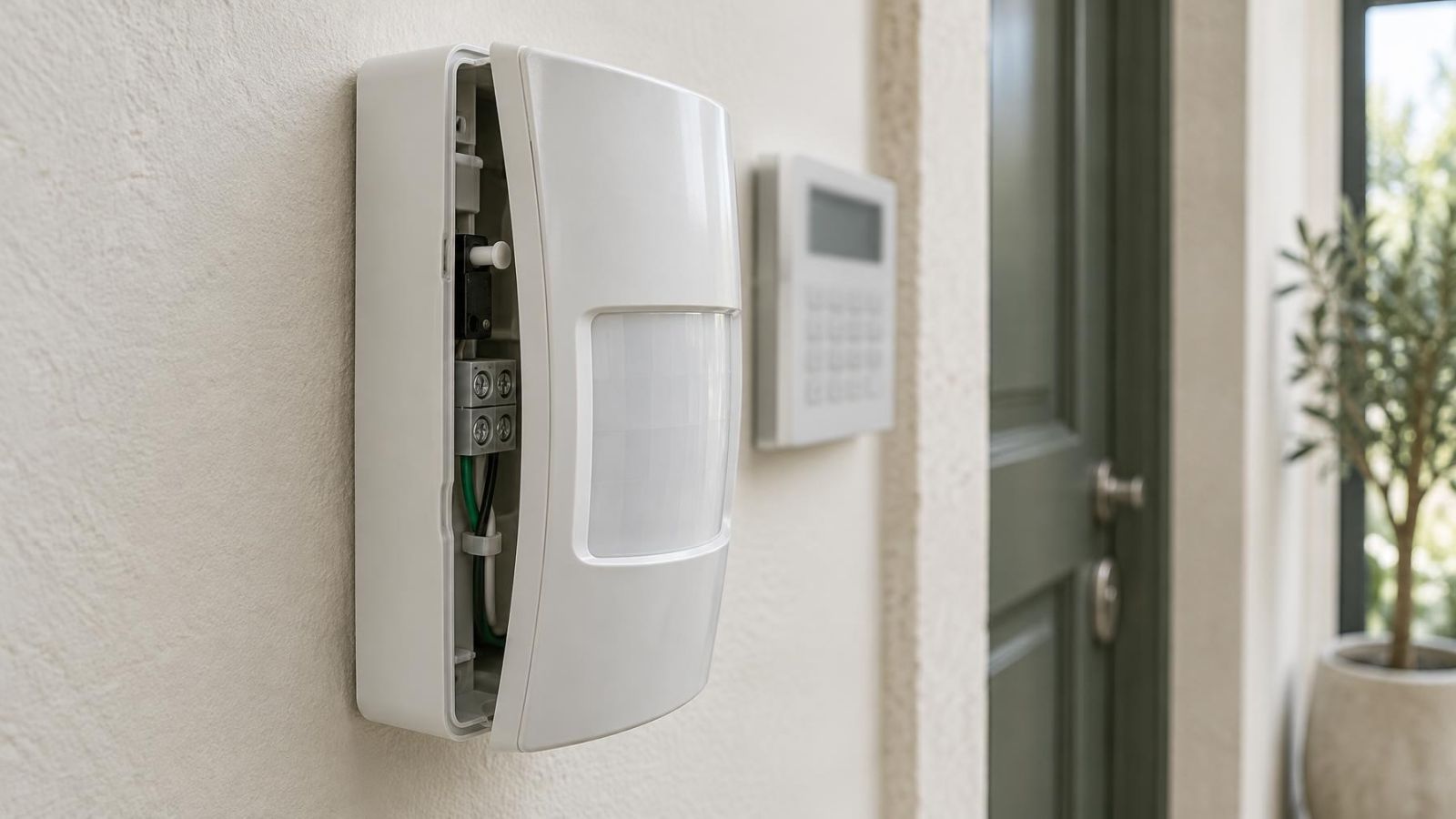
A cover can look closed while its tamper switch remains unpressed. Plastic housings can sit slightly out of position, a cable can become trapped along an edge, or one side can engage while the opposite side remains raised. The small amount of movement may be enough to keep the tamper circuit open.
- Remove and reseat an accessible detector cover only if it is designed for routine user access. Align its clips and edges before tightening any fastener.
- Check the alarm control panel door from the outside. Look for a bent edge, trapped cable or fastener that does not pull the enclosure squarely closed.
- Check that a wall-mounted keypad sits flat against its backplate. A loose backplate may fail to press a rear tamper switch.
- Inspect accessible siren housings from a safe position. Stop if access requires climbing, work near electrical equipment or exposure to a drop.
- Look for missing, loose or damaged screws and clips. Use only the intended fixing points; an unsuitable fastener can distort a housing.
- Where visible without reaching into powered equipment, check whether the tamper switch moves freely and lines up with the part of the cover intended to press it.
Do not tape down a switch, wedge it closed or bridge its terminals. Such measures can make the message disappear while leaving the enclosure without tamper supervision. A sticking or misaligned switch needs adjustment or replacement, not permanent restraint.
Inspect connections and exposed wiring
If every accessible cover is correctly seated, inspect the visible cable path. Loose terminals, damaged cable and damp junctions can produce either a constant fault or an intermittent message. Restrict user checks to areas that are safe and clearly identifiable. Terminal testing and repairs inside powered equipment are technician work.
- Look for a conductor that has slipped partly out of an accessible low-voltage terminal or has been clamped on its insulation instead of bare conductor.
- Follow visible cable for cuts, crushed sections, tight bends and places where a fixing has pressed into the sheath.
- Inspect an accessible junction box for damp, corrosion, loose joins or discoloured conductors. Do not disturb wet electrical equipment.
- Pay close attention where a cable crosses a moving door, gate or shutter. Repeated bending can damage conductors inside an intact-looking sheath.
- Look for gnaw marks, disturbed cable clips or debris that may indicate pest damage in roof spaces, cupboards or service voids.
- Check whether recent decorating, shelving or maintenance could have moved a cable or junction, without assuming that timing proves the cause.
Intermittent faults often react to gentle movement, temperature changes or vibration. Record any relationship instead of pulling the cable to force a result. A conductor can make contact in one position and open again later, so a temporary restore does not confirm a repair.
Narrow down a shared tamper circuit
Several detectors, junction boxes or alarm devices may be wired in one tamper loop. Any open switch or broken conductor in that loop can produce the same keypad fault. The displayed zone may therefore describe the circuit or protected area rather than the exact component.
List every device known to share the affected run. Include accessible junction boxes and less obvious enclosures such as expansion units or power-supply housings. If the fault changes while one enclosure is handled, note the result, but confirm it more than once before treating that device as the cause.
- Use labels, drawings and visible cable routes to establish which devices may share the loop. Do not rely only on the keypad name.
- Inspect accessible devices in circuit order where the route is known. Check each cover, switch and visible connection before moving to the next.
- Record where the fault restores or returns during inspection. A change near one device may still come from a cable or junction feeding the next device.
- If no physical defect is visible, have a qualified alarm technician isolate sections of the loop and test them zone by zone. Isolation should be temporary and controlled.
- After the faulty section is identified, restore the complete supervised circuit and verify every disturbed enclosure.
The end-of-line resistor is important because its position determines how much of the wiring the panel supervises. It is normally intended to sit at the monitored end of the circuit, not simply at the easiest terminal. If it has been moved into the control panel or an early junction box, cable faults beyond that point may be harder to distinguish from enclosure faults.
Clear and verify the fault
Some panels clear a tamper indication as soon as the circuit closes. Others retain it until the physical problem has been corrected and a panel reset is performed. Resetting first may clear the display briefly, but it does not repair an open switch, damaged cable or loose connection.
- Close every detector, keypad, junction box and equipment enclosure disturbed during testing. Confirm that clips, hinges and fasteners are fully engaged.
- Use the normal user reset procedure if the panel requires one. Do not use service commands whose purpose is unclear.
- Read the keypad again and review the latest event-log entries. Look for a tamper restore without a new fault following it.
- Arm and disarm the system through its normal user controls more than once, allowing enough time for the display and event log to update.
- Check the system again after normal movement of any related gate, door or shutter. The fault should not return when the cable or enclosure moves in ordinary use.
Do not leave the tamper circuit bypassed to obtain a clear display. A bypass removes supervision from the affected enclosure or cable. If the system must remain partly usable while a repair is arranged, any temporary configuration should be understood, documented and restored by the person responsible for the technical work.
When should you stop troubleshooting?
Stop when the next step requires access that is unsafe, unfamiliar or likely to obscure the original fault. A methodical diagnosis is more useful than a sequence of unrecorded changes. Some faults cannot be separated without circuit testing and reliable wiring information.
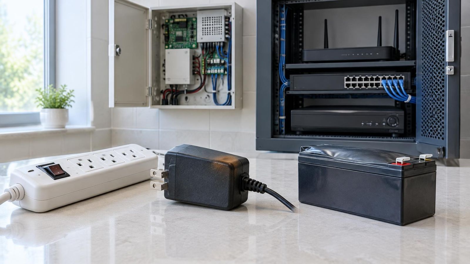
- The suspected fault is inside the alarm control panel, behind an internal barrier or near the incoming power section.
- The external siren cannot be reached from a stable working position or may sound while it is being opened.
- Wiring is damaged, wet, unlabelled or joined in a way that cannot be followed confidently.
- The tamper message appears and disappears without a repeatable relationship to a cover, cable or moving structure.
- Several zones change together, suggesting a shared connection, expansion unit or power issue rather than one detector.
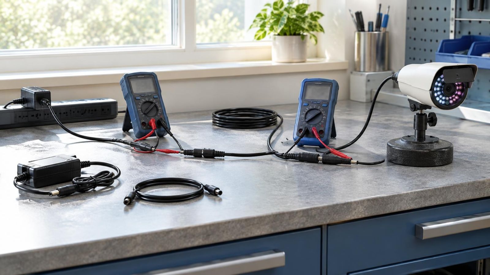
- Diagnosis requires resistance measurements, zone-by-zone isolation, programming access or confirmation of the end-of-line resistor arrangement.
A qualified alarm technician can test each section without permanently defeating supervision, identify whether the problem is mechanical or electrical, and return disturbed wiring to a clear, documented state. Provide the keypad wording, event-log sequence, photographs and notes about what changes the fault. Those details reduce unnecessary dismantling and help preserve intermittent evidence.
Key takeaways
- The exact keypad message and system event log provide the best starting point for tracing a tamper fault.
- Enclosure fit should be checked before wiring because a closed-looking cover may not press its tamper switch correctly.
- A shared tamper loop must be treated as a complete circuit rather than as a fault in one named device.
- Permanently bypassing a tamper circuit removes supervision instead of repairing the fault.
- Troubleshooting should stop when diagnosis requires unsafe access, work inside the control panel or testing of unclear wiring.