On this page
When outdoor security cameras are planned for a home entrance or garden gate, the camera placement plan must connect three things: the required field of view, the physical mounting point and a workable cable route. Camera sightline planning settles what each camera must show, which objects may block it and whether the real image remains useful before any holes are drilled.
Define Each View in Camera Sightline Planning
Start with the target, not the camera. “Cover the front garden” is too vague. “Show people approaching the gate, then provide a closer view at the entrance” gives each position a clear purpose. The useful view is the one that shows the required detail at the relevant distance, not simply the widest possible scene.
List the places where people or vehicles enter, pause or change direction. For a private home, these may include the pedestrian gate, driveway, path, front door and garden access. In an apartment building, they may include the shared entrance, lobby and route to a private door. A street-front business may need separate views of the doorway, service counter and exterior approach.
Where should an outdoor camera be mounted?
An outdoor camera should be mounted where it can see the intended target at a useful angle while remaining accessible for maintenance. Excessive mounting height often produces a clear view of the top of a person’s head but weak detail of the face. A lower position may provide better detail, but it still needs protection from casual contact, moving gates and routine activity.
Consider movement through the property rather than treating every location as an isolated picture. A person may move from a garden gate through a shaded path to a bright entrance. Adjacent views should follow that route with useful overlap. Coverage should also stop where it no longer serves the agreed purpose, particularly around neighbouring windows, private gardens and shared apartment areas.
How Do You Plan Camera Sightlines?
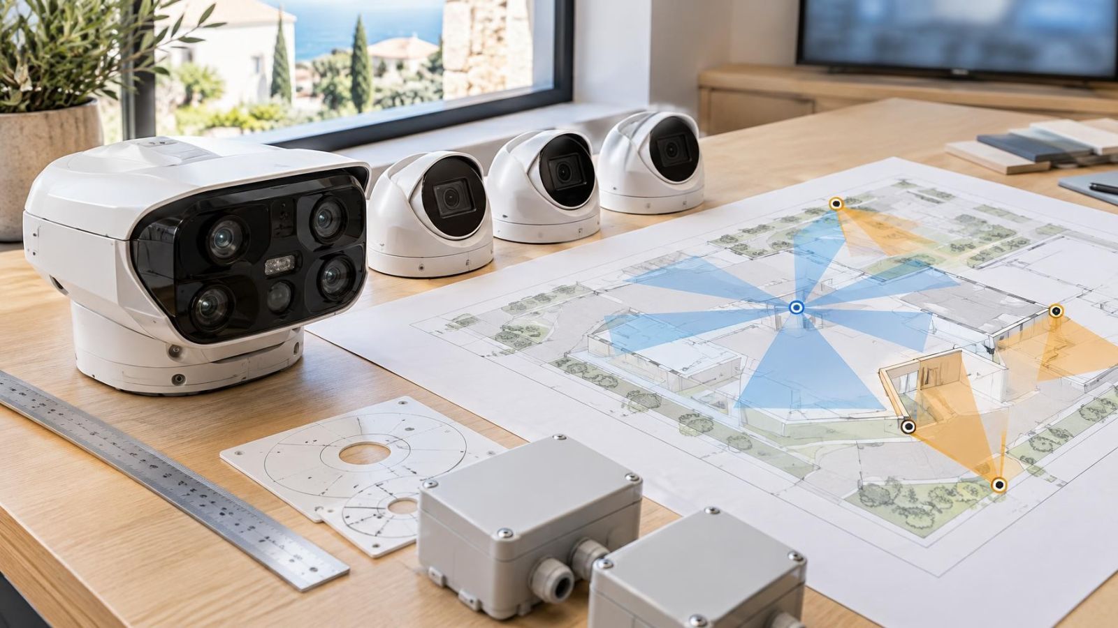
A simple sketch is usually enough to begin a security camera layout. It does not need architectural precision. Draw the building outline, garden walls, gates, doors, windows, parking positions and property boundaries. Add shared corridors or entrances where relevant. For a business, include the frontage, display areas, counters, shelving and service doors.
Mark every proposed camera position with an arrow showing its viewing direction. Then draw a rough viewing cone. The cone is not a promise of visible detail across the entire area; it is a reminder to check what enters the frame and how far the main target sits from the lens.
The sketch should also show possible power and network routes. A position that looks ideal on paper may require exposed cable, an awkward crossing over a doorway or a route through a difficult internal wall. Marking the route early prevents the visual plan and the installation plan from drifting apart.
Use the following sequence when preparing the map:
- Draw the property boundaries, building edges and main internal divisions.
- Mark entrances, gates, approach paths and the places where people are expected to pause.
- Place each proposed camera and show its viewing direction.
- Write the purpose of the view beside the camera, including the target and required detail.
- Add likely power, network and cable routes without treating them as final.
- Walk the property with the sketch and correct anything the drawing has simplified.
Mark Fixed and Changing Obstructions
A camera view obstruction may be part of the building or something that moves. Fixed obstructions include walls, columns, roof edges, awnings, drainpipes and deep window recesses. They are usually easy to draw, but their effect can be difficult to judge from below. A small roof edge near the lens can occupy a large part of the final frame.
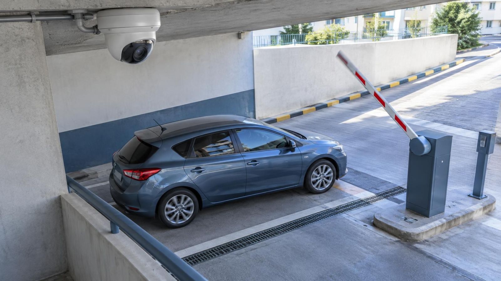
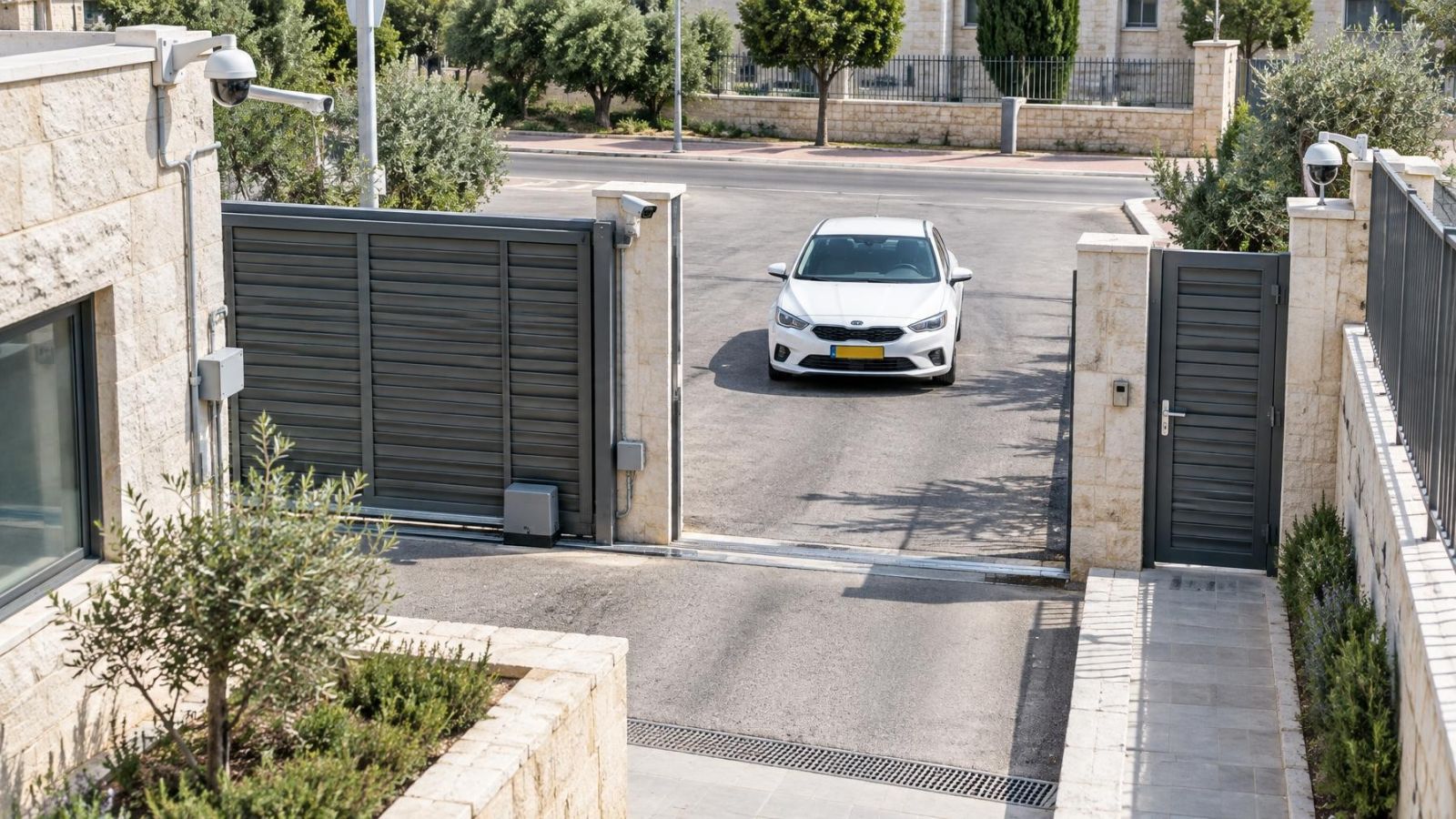
Changing obstructions need a separate check because they may not be present during the first visit. Test gates in both their open and closed positions. Consider where residents, staff or customers normally park. A camera aimed across a driveway may show the intended target when the space is empty and little more than a vehicle when it is occupied.
Trees, climbing plants and garden shrubs change shape and move in wind. Leave enough separation that ordinary growth does not immediately enter the main viewing area. At a street-front business, include movable signs, window displays, awnings, shelving and stock placed near the entrance. An operational layout is more useful than a view designed around an unusually empty space.
How can you find blind spots before installation?
Walk the normal routes through the property while someone watches the proposed views from each marked position. Check corners, recesses, areas behind columns and the space immediately below the camera. Repeat the walk with gates open, vehicles parked and movable displays in their usual positions. Blind spots often appear at transitions between cameras rather than in the centre of a view.
Check Light Before Choosing Angles
Strong Israeli sunlight can turn a sensible drawing into a difficult image. Note the direction of the sun across the day and identify cameras that would face a bright sky, reflective wall or sunlit street. The problem is not only glare. A shaded entrance against a bright background can create deep contrast, leaving the doorway with much less visible detail.
How does direct sunlight affect a camera view?
Direct sunlight can create glare, wash out parts of the scene and force the camera to balance very bright and very dark areas in one frame. WDR (wide dynamic range) can help manage contrast, but it cannot correct every angle. Changing the viewing direction, reducing the amount of sky or placing the main target away from the brightest background is often the cleaner solution.
Glass requires a real test. A camera looking through a window may record reflections from indoor lights, illuminated signs or objects behind the camera. At night, built-in IR can reflect from the glass and dominate the image. If a camera must view through glass, test it with the indoor and outdoor lighting in their normal operating states. Turning off IR may help, but the remaining light must still support the required view.
Outdoor lights also affect framing. A lamp close to the lens can attract insects and create a bright foreground area. A wall-mounted light inside the frame may influence exposure more than the distant target. Check the image with exterior lights both on and off rather than assuming the darker condition is the only relevant one.
Match View Width to Purpose
Wide coverage and target detail compete with each other. A broad view provides context, but the person, doorway or vehicle within it occupies less of the frame. A narrower view gives the target more image area while showing less of the surrounding scene. Lens width should therefore follow the purpose of the position.
| Purpose | Preferred framing | Main risk to check |
|---|---|---|
| Approach overview | Broad scene showing direction of travel | Main target becomes too small in the frame |
| Entrance detail | Tighter view centred on the doorway or gate | Opening door or gate blocks the target |
| Driveway context | View covering vehicle movement and access points | Parked vehicles dominate the foreground |
| Interior activity | Defined work or customer area | Shelving, displays or bright windows obscure the scene |
Target distance matters as much as viewing angle. A camera can technically include a distant gate while providing little useful detail there. Mark the primary target and judge the live image at that exact point. Do not evaluate only the sharp foreground wall, path or parked car.
Foreground objects deserve particular attention because objects close to the lens appear disproportionately large. A column edge, roof beam, hedge or open door may consume much of the frame. At night, a nearby pale wall can reflect IR back towards the camera, making the foreground bright while the target remains dark.
Adjacent views should overlap at meaningful transition points. The overlap does not need to duplicate two entire scenes. It should cover the route where a person or vehicle leaves one useful frame and enters the next. This is especially important around garden corners, building entrances and narrow passages beside a home.
How Do You Test Before Fixing?
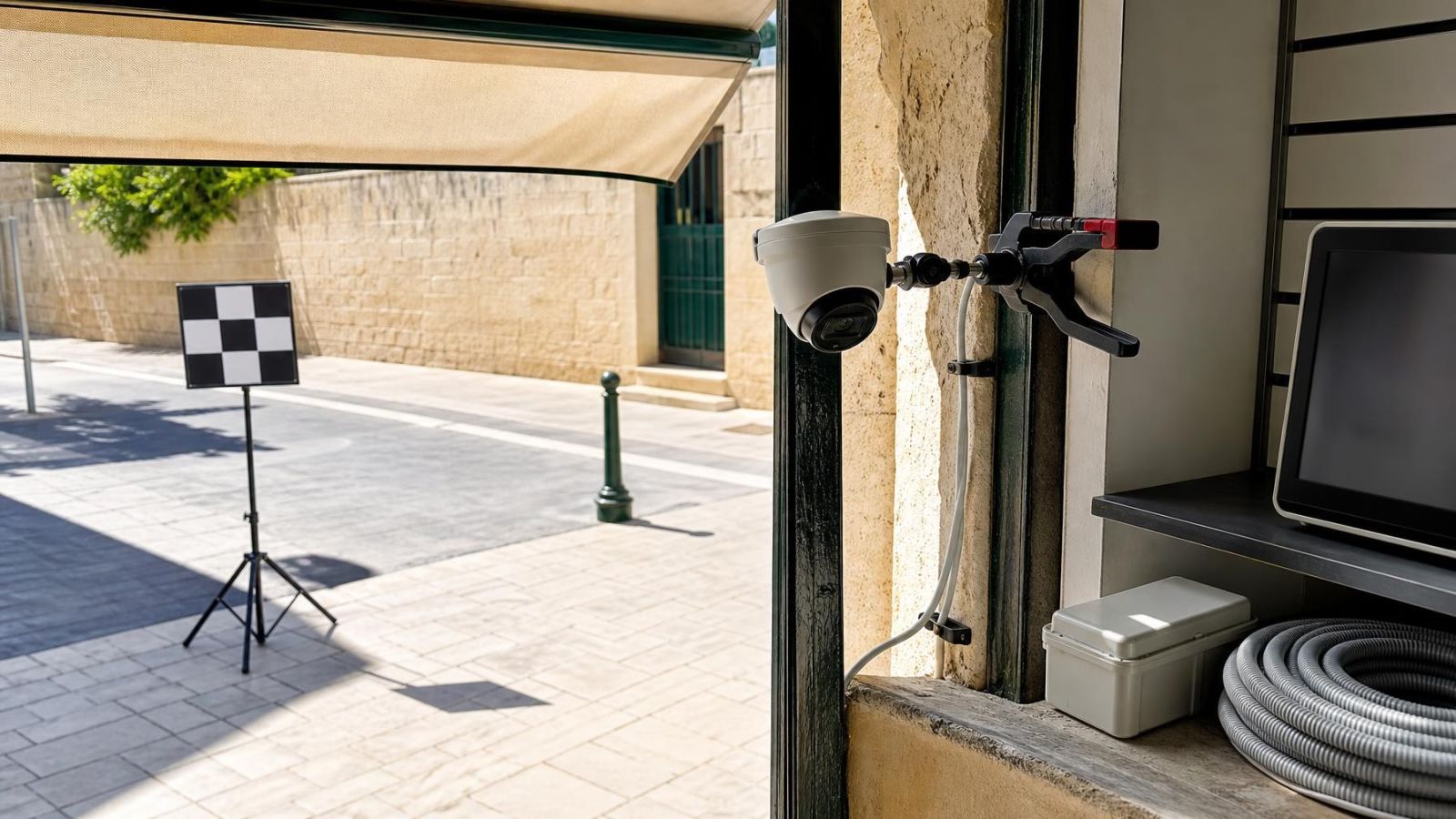
Test the actual camera from the intended position before fixing the mount. A temporary camera test reveals framing problems that a floor plan cannot show, including roof edges near the lens, unexpected reflections, insufficient target detail and objects that dominate the foreground.
How do you test a camera angle before fixing the mount?
Use a stable temporary support or have an installer hold the camera safely at the intended mounting height. View the live image rather than judging along the body of the camera. Small differences in position and tilt can change the frame substantially, particularly near walls, soffits and narrow entrances.
A practical test follows the way the property is used:
- Place the camera at the proposed height and distance from the wall edge.
- Open the live view and confirm the primary target before adjusting for general scene width.
- Walk the approach path and pause at the gate, entrance or other defined target.
- Operate gates and doors through their normal movement and check both end positions.
- Place vehicles, signs or movable objects where they are normally found.
- Repeat the image check in daylight and with the normal exterior or interior lights operating.
- Make the final lens and framing adjustment, then capture the approved view for reference.
Do not rely only on a handheld test from ground level. Raising the camera changes the angle to faces, the amount of sky in the frame and the way awnings or roof edges intrude. The live image should come from the intended height, even if the temporary support is less convenient.
Reconcile Sightlines With Installation
The final position must support both the view and the infrastructure behind it. For a wired network camera, confirm that power and network connectivity can reach the location. PoE (power over Ethernet) can carry both over one network cable, but the cable still needs a protected, maintainable path back to the network equipment or NVR (network video recorder).
Avoid routes that leave cable exposed to routine contact, gate movement, sharp edges or standing water. Exterior junctions should be placed where they are protected and can be reached for inspection. A neat route is not only visual; it reduces the chance that future maintenance will require opening finished surfaces unnecessarily.
Access to the camera matters after installation. The lens may need cleaning because of dust, coastal humidity or garden debris. Connections may need inspection. A position directly above a delicate awning, deep planter or permanently occupied display can make ordinary service unnecessarily difficult.
Mamad safe-room walls and other dense structural elements can make internal cable routes less direct than they appear on a plan. Identify them before selecting the route. It may be more practical to approach from an adjacent ceiling space, service area or external path, provided the resulting position still meets the viewing requirement.
Shared apartment entrances require coordination with the people responsible for the common area, often the va'ad bayit. Agree on the proposed position, visible cable route, area included in the frame and access needed for future maintenance. A marked plan and sample live view make the discussion more concrete than a verbal description.
Approve the Map Before Drilling
Approval should cover the complete map, not just individual camera locations. Confirm that every view has a named target, that the required detail is visible there and that adjacent cameras connect without avoidable gaps. Remove or reposition movable obstructions where practical, but design around objects that are part of normal daily use.
Review privacy boundaries at the same time as coverage. Check neighbouring properties, shared corridors, staff-only areas and parts of the home that do not belong in the frame. Adjust the angle or narrow the view where the extra area adds no operational value.
Record the approved camera position, mounting height, viewing direction, final frame and cable path. Photographs of the temporary view are useful when clearly labelled. The record helps the installer reproduce the agreed angle and gives a remote owner or business manager a clear reference for later maintenance.
- Each camera has a defined target and required level of detail.
- Fixed and changing obstructions have been checked in normal operating positions.
- Daylight, direct sun, glass reflections, exterior lights and night vision have been tested where relevant.
- Useful overlap exists between adjacent views.
- Power, network and protected cable paths are workable.
- Maintenance access and shared-area arrangements are understood.
- The complete map and live views are approved before drilling begins.
Drilling should be the last confirmation, not the first experiment. Once the target, real image, lighting, obstructions and cable route agree, the mounting position becomes a practical installation decision rather than a guess based on a drawing.
Key takeaways
- Every camera sightline should be designed around a specific target and the detail required at that location.
- A live image from the intended mounting height should be tested before mounting holes are drilled.
- Sunlight, glass reflections, exterior lights and night vision are part of camera layout planning.
- Obstructions and cable routes should be mapped alongside camera positions rather than checked separately.
- The complete coverage map should be approved before permanent installation begins.