On this page
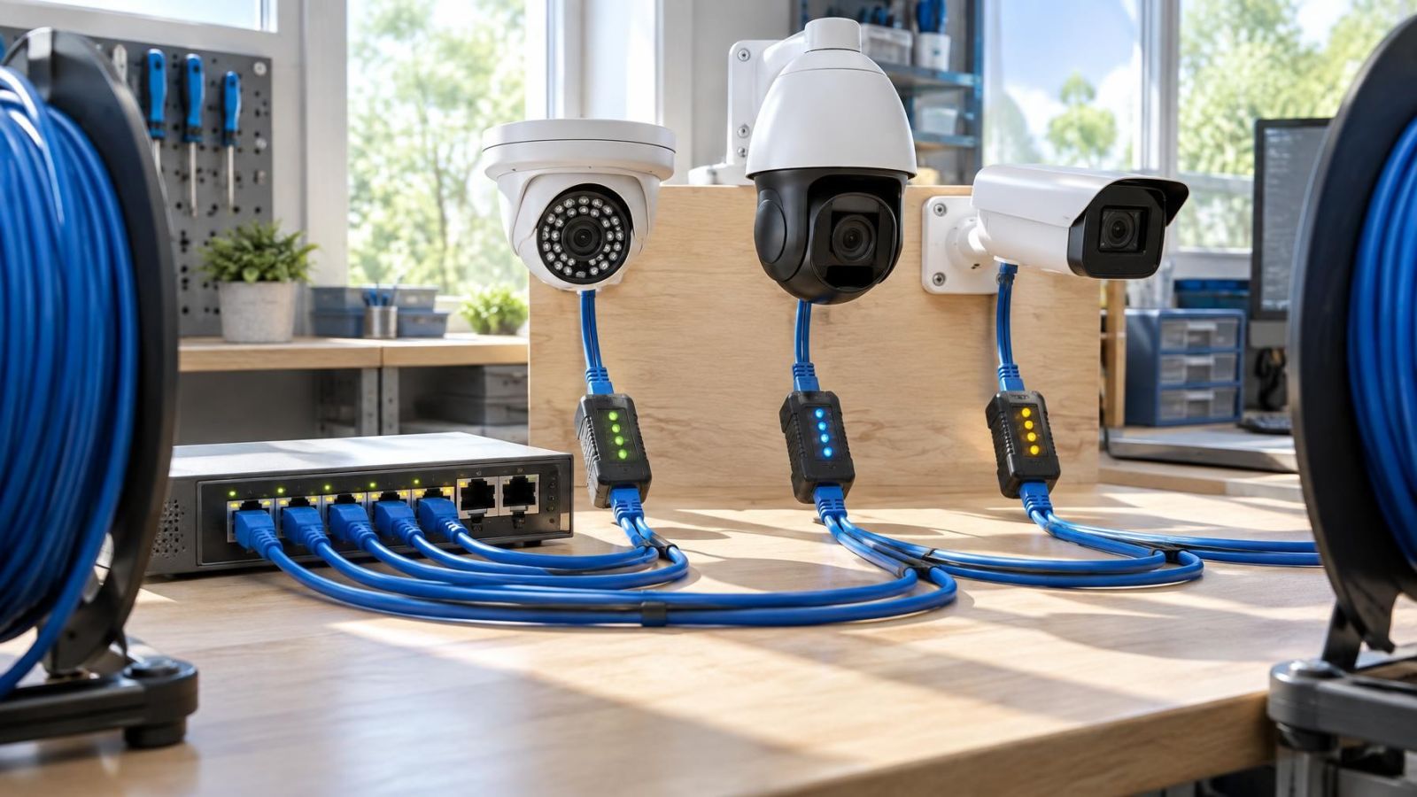
A network camera is connected by Ethernet cable to a PoE switch in the communication cabinet, or perhaps to a separate PoE injector. It works during the day but restarts when its infrared illuminator switches on. PoE power negotiation explains the first part of this system: how the power source recognises the camera and establishes compatible delivery. It does not, by itself, guarantee that the port, shared power supply and cable can support the camera under every operating condition.
What PoE Power Negotiation Actually Does
What does PoE power negotiation do?
Negotiated PoE begins with detection. Before applying normal operating power, the power sourcing equipment checks the cable for the electrical signature of a compatible powered device. In this installation, the source is usually a PoE switch or injector, and the powered device is the security camera.
Detection matters because an Ethernet connection and a PoE power connection are not the same thing. A camera can communicate over Ethernet yet be incompatible with the power method available at the other end. Likewise, a switch port can carry network data without being able to power the connected device.
After detecting a compatible device, the source and camera establish the relevant power capability. The exact exchange depends on the equipment, but the practical result is that the source knows it may energise the connection and the camera knows what power is available. Normal power delivery then begins.
Power and network traffic use the same cable, but they remain separate functions. Video, control commands and status information are network data. Detection and power delivery are electrical processes associated with the cable pairs and PoE circuitry. A working data path therefore does not prove that the power path is healthy.
A passive injector is different. It places power onto selected conductors without performing the same detection and negotiation. It should not be treated as interchangeable with a negotiated source merely because the connectors fit. The voltage, wiring arrangement and connected camera must all be explicitly compatible.
An Ethernet plug confirms a physical connection. It does not confirm that the power method, port capacity and camera demand are compatible.
Port Capacity and Total Power Budget
What determines camera PoE compatibility?
Camera PoE compatibility has several layers. The source must use a power method the camera accepts. The individual port must be capable of supplying enough power. The switch must also have enough total capacity for all powered devices connected at the same time.
The distinction between power per port and the shared power budget is easy to miss. A switch may have a port capable of supporting a demanding camera while its internal supply cannot support that demand on every port simultaneously. Cameras already connected elsewhere on the switch reduce what remains available.
| Power question | What it tells you | What it does not tell you |
|---|---|---|
| Is the camera compatible with the PoE method? | Whether normal negotiated delivery can begin | Whether enough capacity remains under full load |
| Can the port supply the required power? | Whether one port is suitable for that camera | Whether the switch can power every connected device |
| Is the shared budget sufficient? | Whether combined device demand can be supported | Whether the cable delivers adequate power at the camera |
| Is the cable path sound? | Whether power and data have a reliable route | Whether the source itself has enough capacity |
A single-port injector has no group of camera ports sharing one switch budget, but it still has a capacity limit. Its output must match the camera's accepted power method and maximum demand. The injector's own power supply is part of that calculation.
Planning should also include headroom. A spare network port is not necessarily a spare powered port in practical terms. A later intercom, access device, wireless unit or additional camera may need more power than the remaining shared capacity can provide.
Why Camera Demand Changes
PoE camera power is not always constant. The camera may use relatively little while displaying a daylight scene, then draw more when additional hardware becomes active. The specification used for planning should therefore reflect maximum operating demand, not just a typical or observed daytime load.
- An infrared illuminator adds demand when the camera enters night mode.
- A heater or other environmental component may operate only under particular outdoor conditions.
- Motorised zoom, focus, pan or tilt functions can increase demand while moving.
- A microphone, speaker or other audio circuit adds its own load.
- Startup can require a different power profile from steady operation.
This variation is relevant in Israel because local conditions can be demanding in different ways. Strong sunlight can heat exposed equipment and communication cabinets. Coastal humidity and airborne dust can affect connectors and outdoor enclosures over time. A camera facing a dark garden, gate or car park may use infrared for long periods, even if it appears stable during daytime testing.
The transition to night mode is particularly useful during diagnosis. If a camera restarts at approximately the same point that the scene darkens and the IR illuminator activates, increased power demand is a stronger lead than a random network interruption. It is not proof, but it gives the investigation a sensible starting point.
Why Does Negotiation Fail?
Negotiation fails when the source cannot identify a compatible powered device or cannot offer the required power. Sometimes the initial exchange succeeds and the failure appears later, when the camera asks more of the power path. These are related power problems, but they occur at different stages.
- Incompatible power methods: The camera and source use different approaches, or a passive injector is being treated as negotiated PoE.
- Damaged cable: Crushed, sharply bent, corroded or otherwise impaired conductors can interfere with detection, delivery or data.
- Poor termination: A weak contact may pass some traffic yet become unreliable when current demand rises.
- Insufficient port capability: The source recognises the camera but the port cannot provide the required level of power.
- Exhausted shared budget: The switch can power the camera alone but not alongside all other connected devices.
- Equipment fault: The injector, switch port, camera input or an associated power supply may be defective.
Cable resistance also matters after successful negotiation. Every cable path has some loss. Longer routes, poor copper conductors, damaged sections, unnecessary couplers and weak patch leads can increase voltage drop. The source may appear healthy in the cabinet while the camera receives inadequate power at the far end.
Installers therefore look beyond the permanent cable in the wall or conduit. The short patch lead inside the communication cabinet and the final weather-protected connection near the camera are part of the same electrical path. Either can create an intermittent fault.
Recognising a Power-Side Problem
A power-side fault often follows a change in camera load. Rebooting when night mode begins, dropping offline during motor movement or becoming unstable when audio is used all justify checking delivery. A camera that remains stable with optional functions disabled provides another useful clue.
Network and power symptoms can overlap because a camera that loses power also disappears from the network. The pattern of the failure matters more than the simple fact that the camera is offline.
| Observed behaviour | Power-side interpretation | Network-side interpretation |
|---|---|---|
| Camera restarts when IR activates | Higher demand may exceed available delivery | Less likely if timing consistently follows night mode |
| Link indication remains but camera does not operate correctly | Some Ethernet circuitry may remain active despite unstable camera power | A software or data-path fault is still possible |
| Fault moves when the camera is placed on another port | Original port or available switch capacity may be involved | Original port configuration may also be involved |
| Fault remains on the same cable with another suitable camera | Cable path or termination becomes a stronger suspect | Cable data performance may also be impaired |
| Several cameras fail as more devices are connected | Shared power capacity may be exhausted | Switching or network configuration may also need review |
A stable link light is not conclusive. It shows that part of the physical Ethernet connection is present. It does not confirm that the camera receives clean, adequate power during startup or under maximum load. Conversely, packet loss, address conflicts or VLAN configuration problems can interrupt video while the camera remains properly powered.
Useful diagnosis changes one variable at a time. Moving both the camera and cable to a different switch at once may restore operation, but it does not identify which component caused the fault.
- Record when the failure occurs and which camera functions are active.
- Check the camera's documented power method and maximum demand against the source.
- Move the connection to a known-suitable port with adequate available capacity.
- Test with a known-good short Ethernet cable near the switch or injector, where practical.
- Substitute one compatible source or camera at a time to see whether the fault follows the component.
- Return to the installed cable path and inspect every termination, coupler and patch lead.
Planning the Camera Power Path
How should Ethernet camera power be planned?
Plan power from the camera back to the electrical supply, not only from the switch port outward. The path includes the camera input, outdoor connector, permanent Ethernet cable, patch panel or coupler, cabinet patch lead, PoE switch or injector, and the source's own power supply. Reliability depends on the complete chain.
Start with documentation for each camera. Note the accepted PoE method, maximum power requirement and any functions that increase demand. If a camera also has a separate low-voltage input, do not assume that its stated input voltage describes what should be placed directly onto the Ethernet cable.
Next, verify the switch or injector explicitly. Confirm the capability of the intended port and the total power available across the source. Add the maximum requirements of devices that can operate together. Leave usable capacity for later additions and for changes in the equipment connected to the network.
Review the physical route before closing walls, ceilings or external conduit. Avoid unnecessary joins. Use properly terminated Ethernet cable intended for the route and environment. At garden gates, perimeter walls and exposed business frontages, protect the final connection from movement, moisture and contamination. A weather-resistant camera body does not make an exposed plug connection equally resistant.
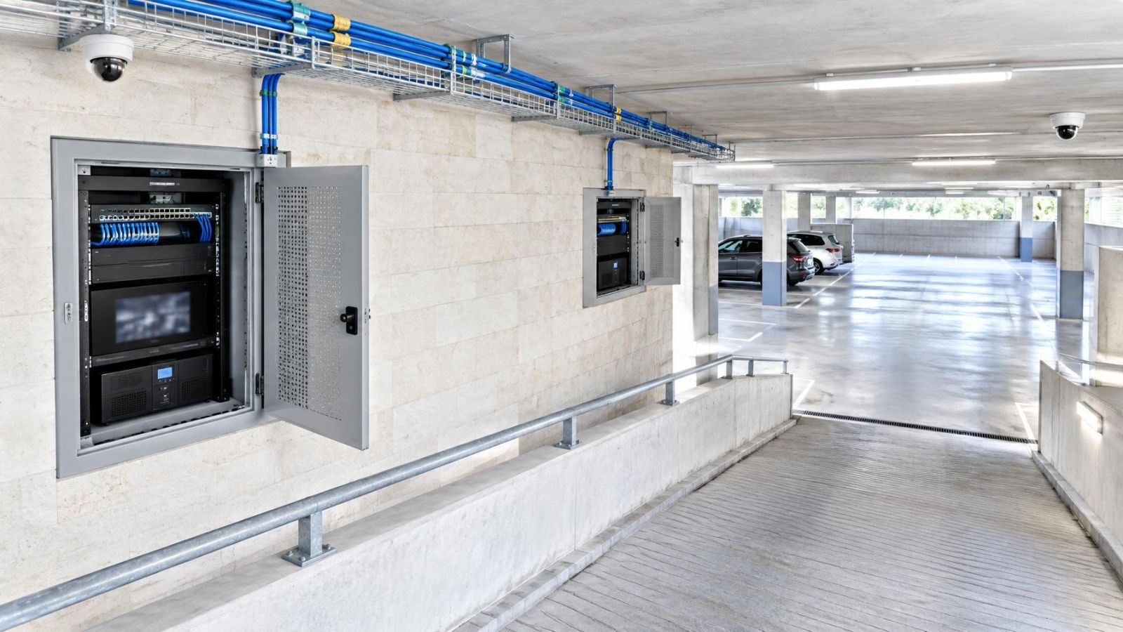
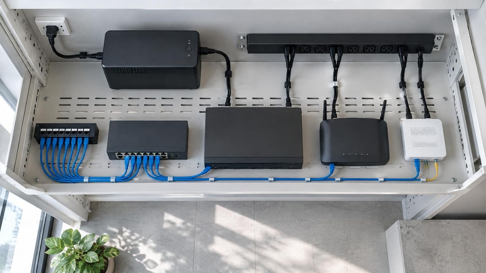
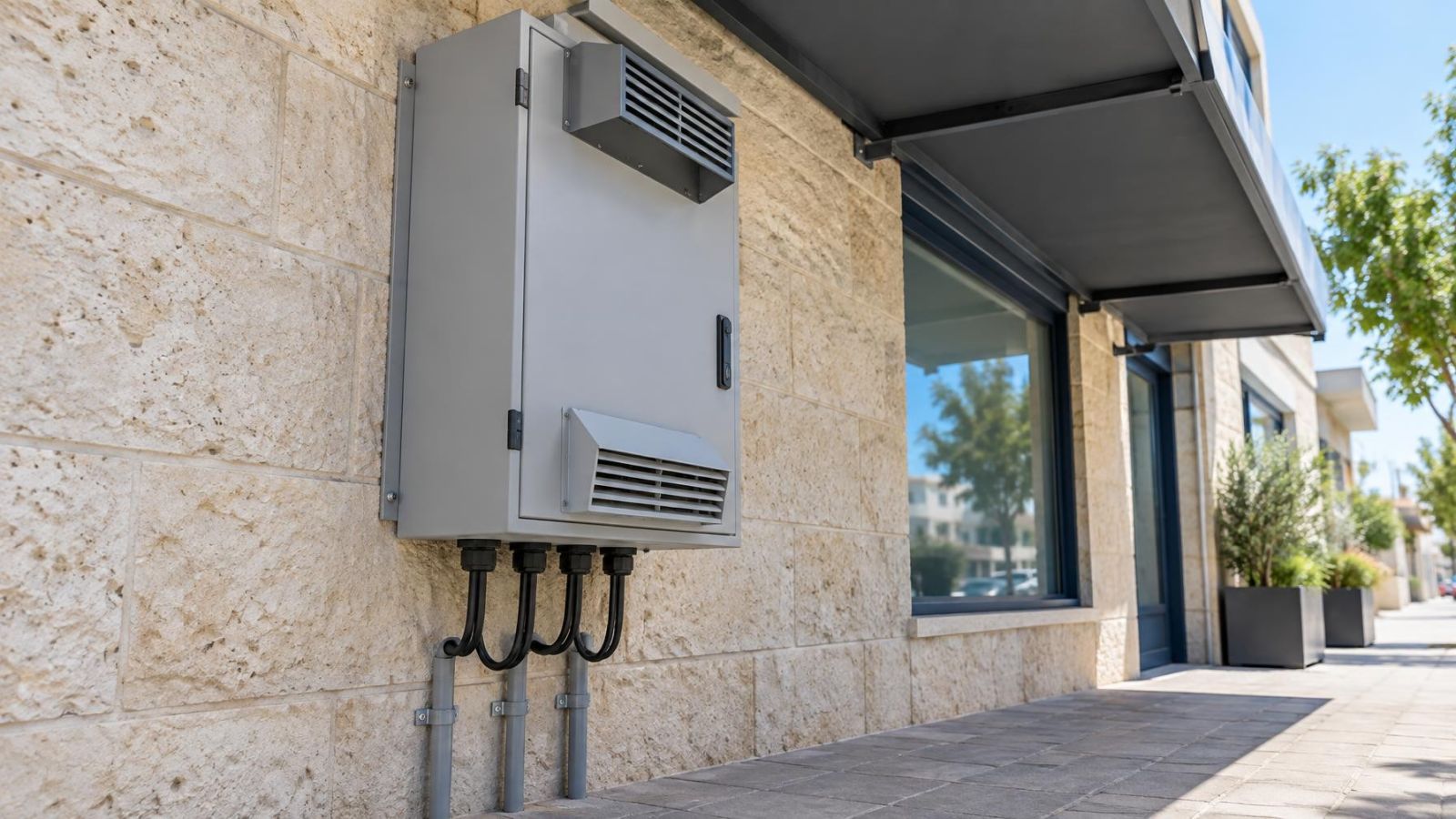
The communication cabinet also deserves attention. PoE power conversion produces heat, and an enclosed cabinet in a warm utility space can make conditions harder for the switch, recorder and power supplies. Provide sensible ventilation, orderly cable management and enough room to inspect or replace patch leads without pulling against other terminations.
In Israeli apartments, confirm where the communication cabinet sits relative to the mamad and to shared building areas. Dense walls and indirect routes can make cable paths longer than they appear on a floor plan. Cameras covering a shared entrance may also connect through infrastructure outside the apartment, so the route and responsibility for each section should be clear before installation decisions are made.
For a private home, include gates, garden walls and detached structures in the power-path review. For a street-front business, consider shutters, signs, direct sun and the practical route back to the cabinet. These details do not change how PoE works, but they influence cable length, connector exposure and cabinet conditions.
Good PoE planning is not simply choosing a switch with many sockets. It is matching the camera's power method and peak demand to the individual port, the shared source capacity and the real cable path. When those parts are checked together, power problems become easier to avoid during design and easier to isolate during maintenance.
Key takeaways
- PoE compatibility depends on successful negotiation, sufficient port capability and enough shared power capacity.
- Camera power demand can rise when infrared illumination, heating, audio or motorised functions become active.
- Ethernet cable quality affects both power delivery and data reliability.
- A camera reboot that coincides with night mode justifies checking the complete power path.
- Camera power requirements should be verified before selecting a PoE switch or injector.