On this page
A PoE switch sits between the IP cameras, the network recorder and the wider network, while the Ethernet cabling carries both data and power back to the technical cabinet. Good PoE switch sizing answers a practical question before equipment is selected: does the planned switch have enough camera ports, power, uplink capacity and installation headroom for the complete system?
Map the Network Before PoE Switch Sizing
Start with the floor plan, not the switch specification. Mark every camera position and give each position a simple identifier. In an apartment, that might include the entrance door, balcony and parking area. In a private home, it may include gates, garden paths and several building elevations. A street-front business may also need indoor views, an entrance view and coverage around a delivery point.
Count Cameras by Location and Function
Record whether each position is indoors, outdoors or in a partly sheltered area. Note the features expected there. A camera facing strong Israeli sunlight may use WDR (wide dynamic range). An outdoor camera may run infrared illumination after dark. A movable camera, an audio feature or another powered function can change its maximum power demand.
The map should also show where the recorder and switches will sit. Some networks use the PoE ports built into an NVR (network video recorder). Others place a separate PoE switch in the technical cabinet and carry camera traffic to the recorder over an uplink. A larger property may use more than one switch to keep cable routes practical.
Plan realistic additions rather than filling the drawing with hypothetical cameras. Useful allowances include an entrance that may later be covered from another angle, an unfinished garden area or a future camera in a shared parking space. In an apartment building, shared-area additions may depend on decisions involving the va'ad bayit, so they should not automatically be treated as confirmed camera positions.
Also consider replacement paths. A future camera may draw more power than the device installed now, even when it uses the same cable and mounting position. The aim is not to guess future equipment. It is to avoid a design that works only with the exact devices on the first list.
How Many PoE Ports Are Needed?
Each directly connected IP camera normally needs one dedicated powered port. The basic count is therefore straightforward: count the camera cable endpoints that will terminate on the switch. Do not count a dual-stream camera twice. Multiple video streams from one camera still pass through one physical network connection.
How Many PoE Ports Do Cameras Need?
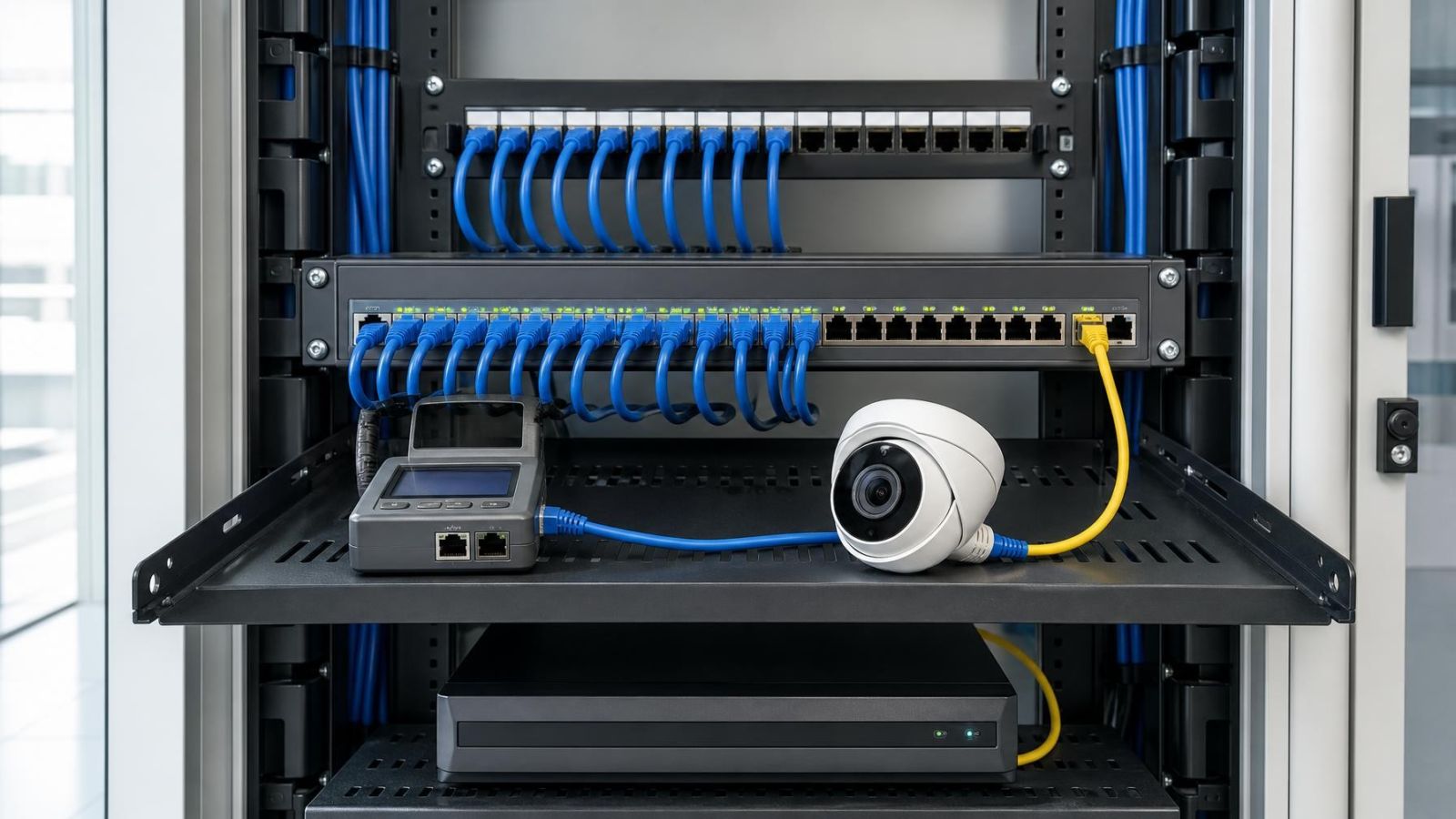
The switch needs at least one compatible PoE port for each camera connected to it. Then account separately for the uplink, the recorder connection and any other network device. These connections may use non-PoE ports, depending on the switch layout and network design.
Read the physical port diagram rather than relying only on the large port-count label. Some ports may have different power capabilities. An uplink connector may share resources with another connector. Cable plugs may also become difficult to release when tightly packed beside cabinet walls, power supplies or neighbouring equipment.
Add spare ports for camera positions that have a credible path to installation. A spare socket has little value, however, if the switch has no remaining PoE power or if its uplink is already carrying the intended maximum traffic. Expansion capacity has three parts: a physical port, available power and available network capacity.
Keep recorder and switch connections visible in the plan. If every camera connects to a separate switch, the recorder generally needs a network path to that switch rather than a dedicated cable from every camera. If cameras connect to recorder-integrated PoE ports, those ports may form a camera-side network that behaves differently from the building's main network.
Calculate the PoE Power Budget
Port count and power budget are separate checks. A switch can have enough powered sockets but still lack enough total output for all connected cameras. It can also have a sufficient combined budget while one port cannot provide the maximum power required by a particular camera.
How Do You Calculate a Camera PoE Budget?
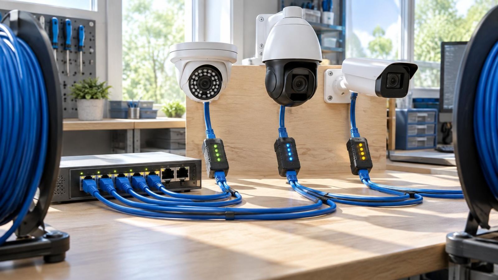
Use each camera's stated maximum PoE demand, not only its typical power consumption. Add the maximum figures for every camera assigned to the switch. Then include operating headroom rather than selecting a switch whose published total merely equals the calculation.
A practical worksheet can use the following sequence:
- List every camera connected to the switch and its maximum input demand.
- Identify cameras with infrared, movement, audio or other features that can increase demand while operating.
- Add the maximum demands to obtain the connected-camera total.
- Check that each individual port can supply its assigned camera.
- Choose a switch with total output above the connected-camera total, leaving usable headroom for operating peaks and planned additions.
The camera PoE budget should reflect the operating state that places the greatest demand on the network. Infrared illumination is a common reason for consumption to rise after dark. Several outdoor cameras can change state at around the same period, so their higher demand should not be treated as unrelated events.
How Much Switch Power Does a Camera Network Need?
Camera switch power must cover the combined maximum demand assigned to the device, with additional headroom. The switch itself also needs an appropriate mains supply and ventilation, but its published PoE output refers to the power available for connected devices. Do not add the switch's own internal consumption to the camera total unless the equipment documentation specifically presents its figures that way.
Headroom should be documented rather than described as simply “some spare power”. Record the connected maximum, the switch's available PoE output and the power reserved for named future positions. This makes later changes easier to assess, especially for a remote property owner who may not be present when equipment is replaced.
Where switches support several PoE power levels, verify both ends of the connection. The switch and camera must negotiate a compatible supply, and the cable must carry it reliably. A high total budget does not make every port suitable for every powered device.
Can the Switch Carry the Traffic?
Power calculations do not answer the bandwidth question. Each camera produces one or more streams, and the traffic usually shares an uplink on its way from the switch to the recorder. The uplink must carry the combined load rather than the load of a single camera.
Follow Every Stream to the Recorder
Estimate stream load using the intended camera settings. Relevant factors include resolution in pixels per frame, frame rate, compression settings, scene activity and the number of streams being requested. A lower-quality secondary stream may be used for phone viewing or a multi-camera screen, while the recorder receives the main recording stream.
Draw the traffic path. If cameras connect to one switch and the NVR connects to the same switch, recording traffic may remain within that device. If the recorder sits elsewhere, the camera streams cross an uplink. If several camera switches feed a central network point, their combined traffic may share another link before reaching the recorder or VMS (video management software).
Check switch capacity at the points where traffic is aggregated:
- The camera-facing ports must support each individual stream load.
- The switch uplink must support the combined traffic that crosses it.
- The recorder connection must accept the intended recording traffic.
- Any link shared by several switches must be assessed using their combined load.
- Remote viewing must be traced from the recorder or camera through the actual network path.
Remote Viewing and Network Separation
Remote viewing does not always add another full copy of every camera stream to the switch uplink. The actual load depends on whether the viewing device requests video from the recorder, from a VMS or directly from cameras. Plan from the intended architecture rather than assuming that all remote access behaves identically.
Cameras are often placed on a dedicated VLAN or another separated network segment. Separation can make addressing, access control and fault-finding clearer, but it does not create extra physical bandwidth. The links between the camera network, recorder and authorised viewing devices still need sufficient capacity.
Do not treat a fast-looking uplink label as the whole answer. The switch must also have adequate internal forwarding capacity for simultaneous camera traffic. For a modest camera network this is rarely the most difficult calculation, but it should still be checked rather than inferred from the number of ports.
Check Cabling and Installation Conditions
A switch and camera can be correctly matched on paper while an unsuitable cable route causes unstable power or data delivery. Ethernet cabling is part of the electrical and network design, not a separate finishing detail. Cable construction, conductor quality, termination quality, route length and physical condition all affect the result.
Inspect Routes, Patch Points and Exposure
Measure the complete channel, including fixed cable and patch leads. Ordinary copper Ethernet links are designed around a maximum channel length of 100 metres. A route close to that limit leaves little room for indirect pathways, cabinet patching or later relocation. For longer routes, redesign the connection rather than assuming a more powerful PoE switch will compensate.
Outdoor runs need cable and containment suited to sunlight, moisture and the route itself. Exposed connectors and casual inline couplers are common weak points. Near the coast, humid and salty air makes cabinet placement and connector protection particularly important. Dust can also collect around open patching and cooling paths.
Count every termination. A camera cable may pass through a patch panel, short patch lead or intermediate enclosure before reaching the switch. Each point should be accessible, correctly terminated and labelled at both ends. Old cable should be inspected rather than accepted because it previously carried a different network device.
Plan Around Mamad Walls and Difficult Pathways
A mamad, the reinforced safe room found in many Israeli homes, can change an apparently simple cable route. Thick reinforced walls, limited conduits and finished interiors may require a longer path around the room. Wireless signal behaviour inside the space is also not a substitute for planning the wired camera connection.
In apartment buildings, the route from a private apartment to a shared entrance, lobby or parking level may cross several building areas and patch points. Confirm the practical path before reserving a switch port for the camera. For private homes, gates and detached structures may be far enough from the main cabinet to justify a different network arrangement.
Plan the Technical Cabinet
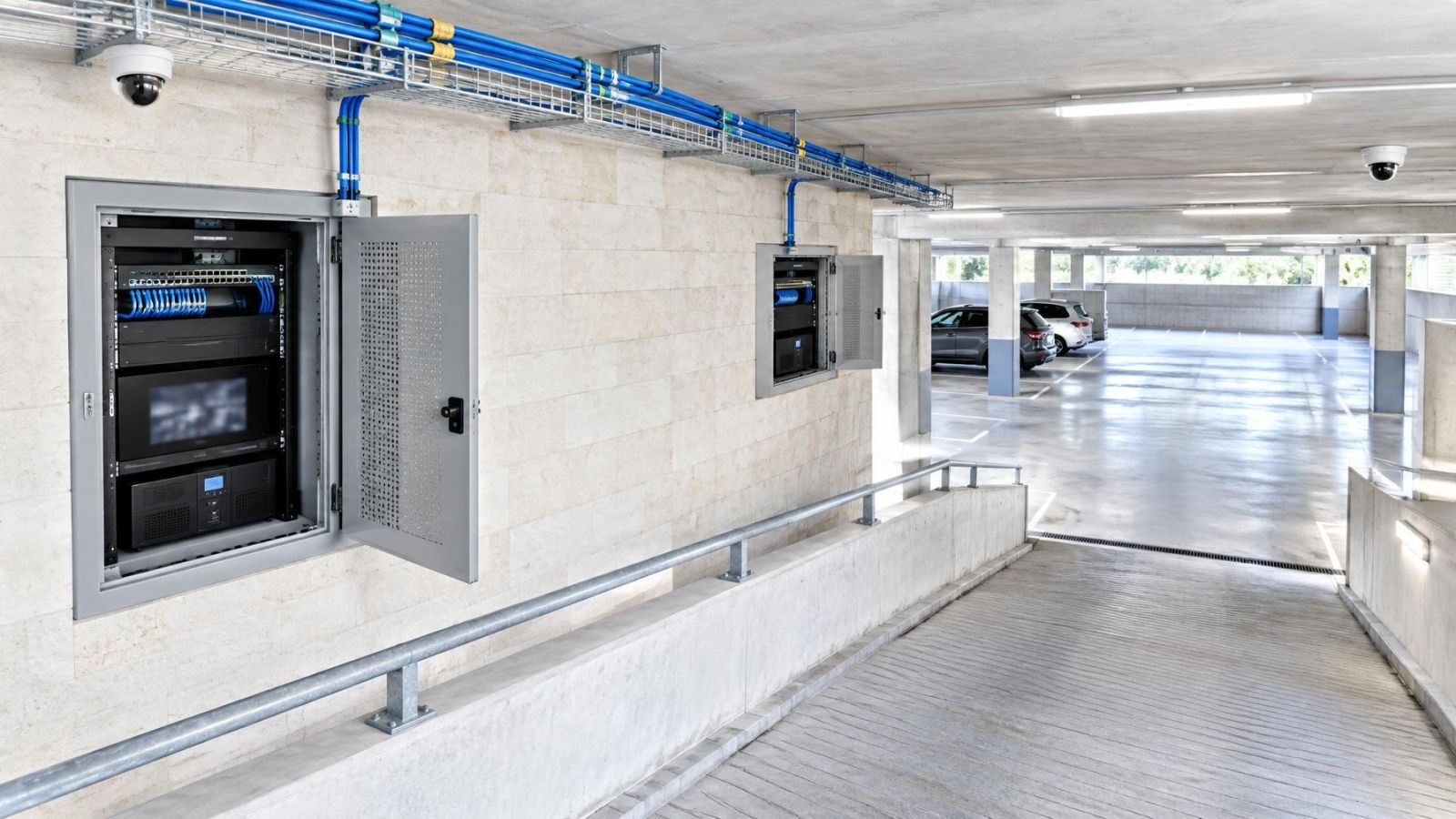
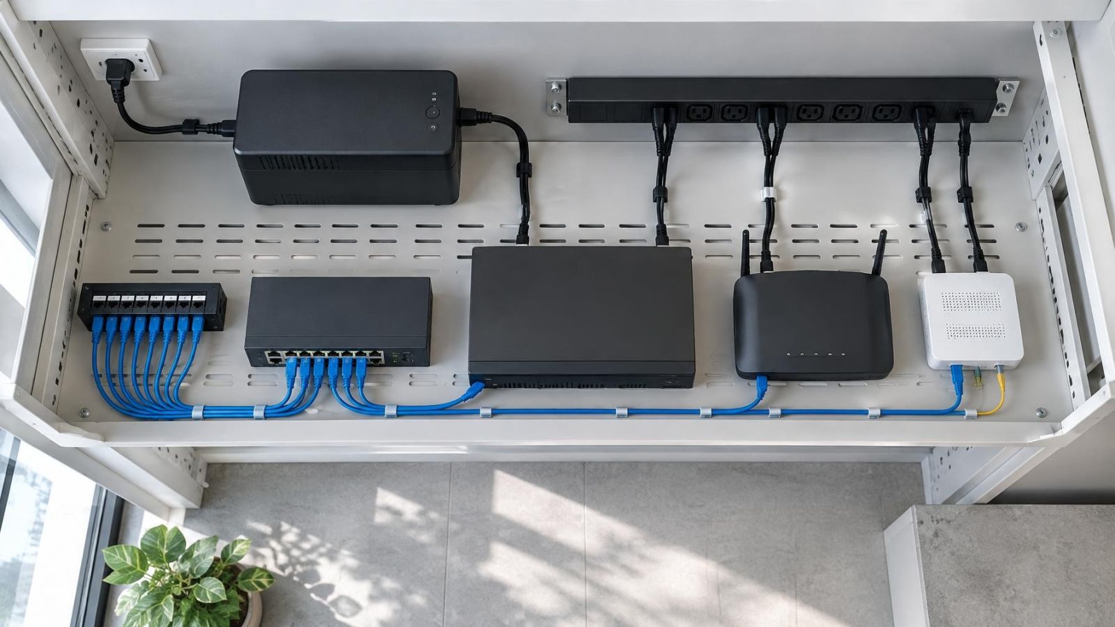
The technical cabinet has to support the complete chain: switch, recorder, router or network connection, patching and power equipment. A cabinet sized only around the front dimensions of the switch often becomes difficult to service once plugs, cable bends and power supplies are added.
Allow for Heat, Dust and Humidity
PoE delivery produces heat in the switch, and the recorder adds its own heat. Leave ventilation space around equipment and keep vents clear of cable bundles. A closed cabinet exposed to strong sun or installed in a hot service area needs particular attention. Cooling should not depend on leaving the cabinet door permanently open.
Dust should be removable without dismantling the camera network. Coastal humidity also favours a dry, protected cabinet location over an exposed utility corner. These conditions influence switch selection because equipment with a comfortable power margin and sensible ventilation is preferable to a densely loaded device operating in a poor enclosure.
Arrange Backup Power and Service Access
If backup operation is required, power the necessary parts of the path. Supplying only the recorder does not keep cameras operating when their PoE switch loses input power. The switch, recorder and any network devices needed for the chosen viewing or recording path must be considered together. Required operating time depends on their combined load and the intended use of the system.
Leave access to status lights, reset controls, uplinks and patch leads. The installer should be able to isolate one camera, test a cable or replace a patch lead without disconnecting unrelated equipment. A clear port schedule fixed inside the cabinet is often more useful than relying on cable colours.
Make the Final Switch Decision
The final choice should come from the completed worksheet, not from port count alone. Verify the required PoE ports, the maximum connected demand, power headroom, uplink capacity, cable routes and cabinet conditions. Record the spare capacity in the same categories rather than describing the switch simply as expandable.
Should a PoE Switch Have Spare Capacity?
Yes, but spare capacity should correspond to plausible changes. A useful final check follows this order:
- Confirm the number of active camera connections and named future positions.
- Confirm that every assigned port supports its camera's maximum demand.
- Add all maximum camera demands and verify total PoE headroom.
- Trace combined stream traffic across every shared uplink and recorder connection.
- Review cable lengths, terminations, exposure and difficult routes.
- Check cabinet ventilation, backup arrangement and service access.
- Document the unused ports, remaining power and available uplink capacity.
If one part fails, changing only the switch size may not solve the design. A distant camera might need a different cable architecture. A recorder connection might need to move to a less congested path. A crowded cabinet might need a better layout before a larger switch is sensible.
Recorder Ports or a Separate PoE Switch?
Both arrangements can be suitable. The better choice depends on the camera count, cable layout, maintenance plan and how much expansion is expected.
| Factor | Recorder-integrated PoE ports | Separate PoE switch |
|---|---|---|
| Initial layout | Direct camera connections at the recorder | Camera connections at a network switching point |
| Expansion | Limited by the recorder's remaining ports and power | Can be expanded or reorganised independently |
| Maintenance | Recorder and camera switching are closely linked | Switch work can be separated from recorder work |
| Network visibility | Camera-side network may be isolated behind the recorder | Camera network can be managed within the planned LAN or VLAN |
| Placement | Camera cables must reach the recorder location | Switch can be placed where cable routes and cabinet conditions suit |
| Failure scope | Recorder or integrated switching work may affect both functions | Recorder and PoE switching remain separate devices |
Recorder-integrated ports can keep a small, fixed system straightforward. A separate PoE switch often makes expansion, cable organisation and maintenance easier, particularly when the recorder is not in the best location for every camera run. Neither layout removes the need to calculate ports, power and traffic.
A spare PoE port is useful only when spare power, uplink capacity and a workable cable route exist beside it.
Key takeaways
- Port count, PoE power budget and uplink capacity require separate sizing checks.
- Camera maximum power demand matters more than typical consumption when calculating switch capacity.
- Spare ports provide useful expansion only when spare power and network headroom are also available.
- Cable routes, terminations and technical cabinet conditions belong in the switch sizing plan.