On this page
You may need an alarm control panel and motion detectors now, security cameras later, and enough network cabling, empty conduit and recording storage to support both. The important decision is not simply which device to buy first. It is how to design a scalable security system whose early phases work properly without limiting the finished installation.
Define the Finished Scalable Security System
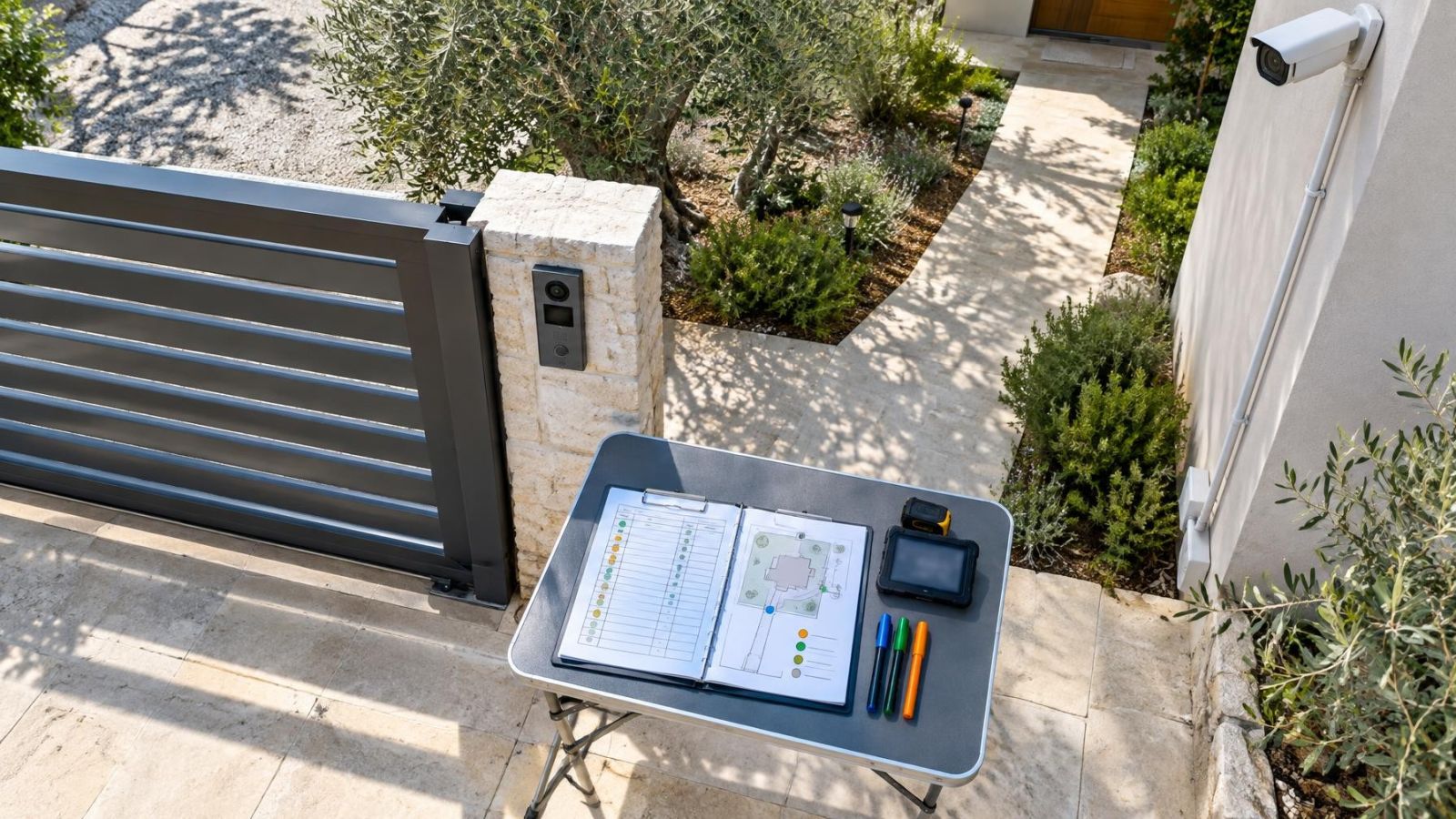
Begin with the intended final coverage. Mark every entrance, gate, garden route, balcony access point, street-facing area and internal zone that may eventually need detection or video. For a small business, include the public entrance, service door, stock or equipment areas, payment position and any street frontage that matters operationally.
Separate the jobs performed by the alarm and the cameras. Motion detectors, door contacts and other alarm devices identify defined conditions and report an event through the alarm control panel. Security cameras produce a visual record. One does not automatically replace the other, so the final drawing should show both systems even if they will be installed at different stages.
- Define the final camera coverage by scene, not merely by the number of camera points.
- Mark alarm detection areas and the openings that may need door contacts or other detectors.
- Rank entrances, gates and street-front positions according to daily operational importance.
- Decide where recording will take place and who needs local or remote access.
- Identify shared-building boundaries before assigning equipment to entrances, lobbies, parking areas or other common spaces.
In an apartment building, a private apartment and the building entrance are different planning areas. Equipment in a shared entrance or common area needs coordination with the va'ad bayit or whoever manages the building. Record that boundary on the plan so private cabling is not designed around an assumed shared installation.
Remote access also needs a clear purpose. A resident abroad may need to review recordings and check system status. A business owner may need separate access for managers and service staff. Decide which users need live viewing, playback or alarm notifications. That decision affects recorder choice, account structure, network planning and the handover process.
Map Sites and Constraints
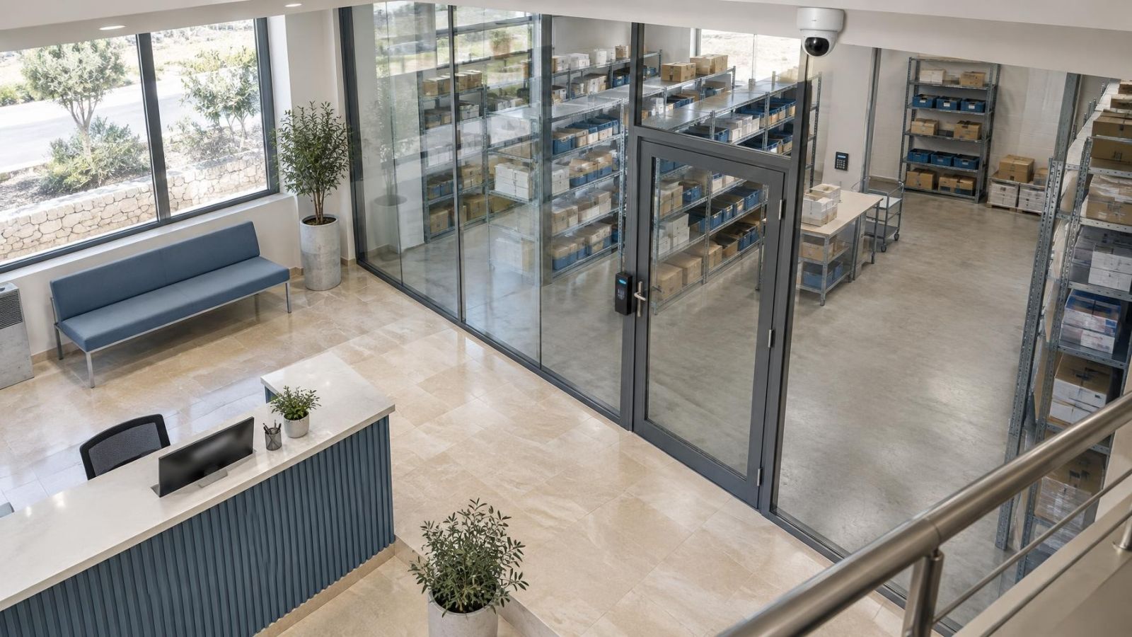
The same equipment plan behaves differently in an apartment, a detached home and a street-front business. An apartment may have limited cable routes and a shared communications cupboard. A private home may require outdoor conduit to a gate, garden or parking area. A shop may need installation work arranged around counters, ceilings, shutters and daily access.
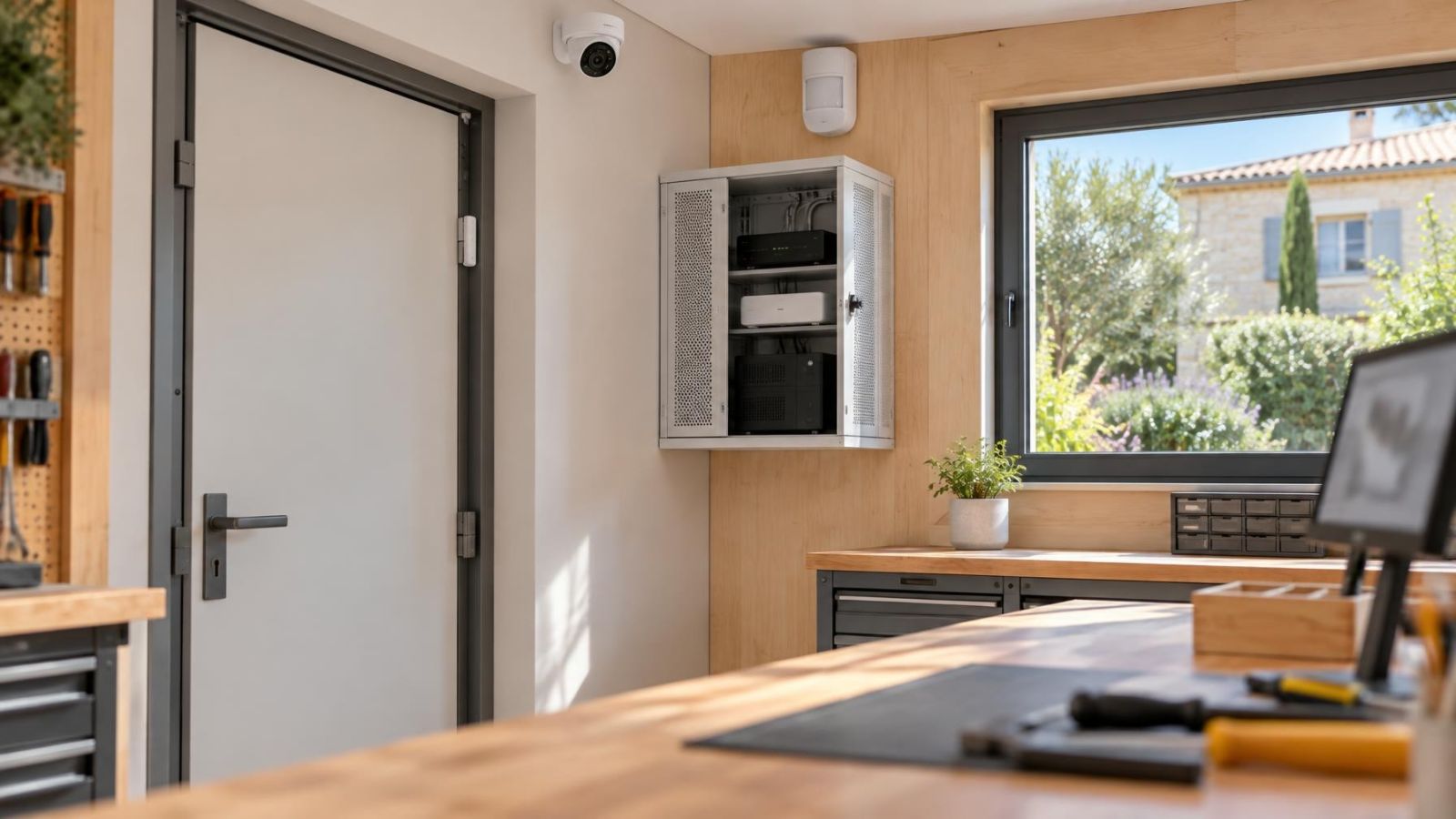
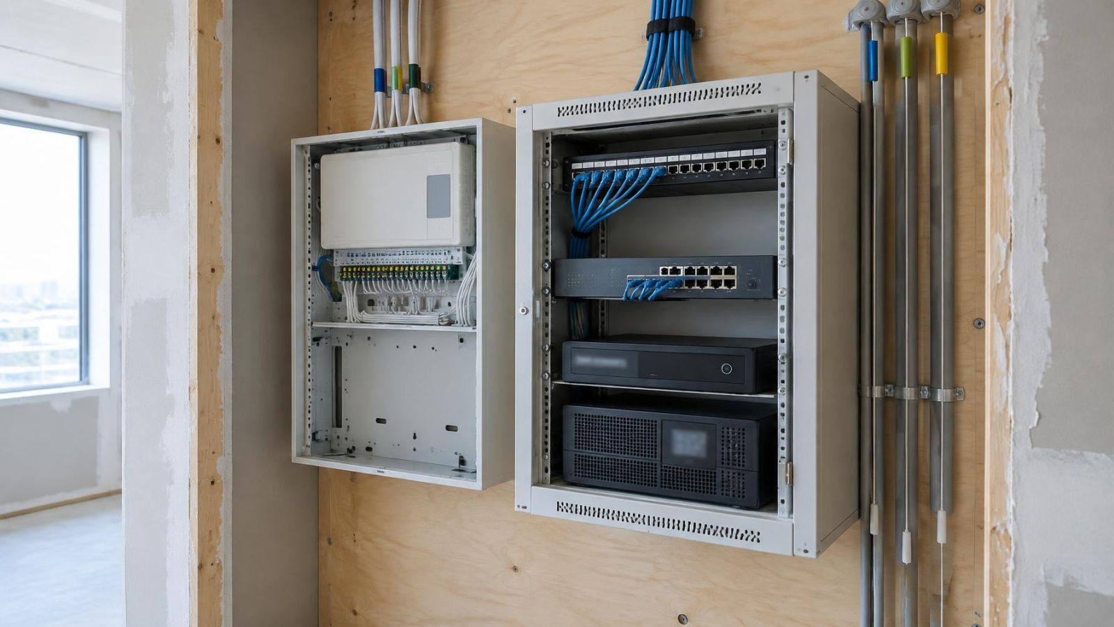
Choose a central equipment location early. It may contain the alarm control panel, an NVR (network video recorder), network switches, power backup and cable terminations. The location should be accessible for service without placing equipment in a passage where it can be knocked, covered or disconnected. It also needs enough physical space for planned additions and sensible cable management.
A mamad is part of many Israeli floor plans and requires specific attention. Its reinforced construction can weaken wireless communication between central equipment and devices on the other side of the room. Do not assume that a wireless detector, camera or network connection will behave the same way through a mamad wall as it does across a normal internal partition. Confirm device locations and communication paths before fixing the central equipment position.
- Check strong sunlight at the actual time and direction from which it reaches the scene. Poor positioning can leave faces or entrances in glare or deep contrast.
- Keep infrared illuminators away from nearby walls, soffits, railings and foliage that can reflect IR into the lens.
- Allow for dust on exposed outdoor equipment and for humid, salty conditions near the coast when choosing locations and maintenance access.
- Identify walls, ceilings and exterior routes that will become difficult to reach after painting, cabinetry, landscaping or other finishing work.
- Confirm that ladders, access panels and equipment doors can still be used after furniture, shelving or signage is installed.
What Should Future Wiring Include?
What counts as future security wiring?
Future security wiring is the cabling and pathway infrastructure needed by planned devices, even when those devices are not part of the current phase. It includes network cable for camera points, alarm cable for detectors and door contacts, conduit for routes that cannot yet be finalised, and provision for power, backup and central termination.
Run network cabling to planned IP camera positions while ceiling voids, exterior walls and garden routes are accessible. PoE (power over Ethernet) can carry network data and power over the same cable, but the cable still needs a complete route back to suitable network equipment. A socket near the camera is not a substitute for a planned data connection.
Alarm wiring should follow the finished detection plan. Prepare routes to likely motion detector positions, external doors, accessible windows, keypads, internal sounders and other intended endpoints. Leave enough service length at each end for termination, but do not hide loose coils where nobody can find them.
- Use empty conduit where the endpoint may move or where later cable replacement would otherwise require opening a finished surface.
- Keep bends and junctions accessible enough for a future cable pull.
- Provide a draw cord in unused conduit and identify both ends.
- Plan central power and power backup for the finished equipment set, not only the devices fitted in the first phase.
- Label every cable at both ends with a unique endpoint name that matches the system drawing.
Avoid vague labels such as camera 1 unless the same name appears consistently on the drawing, recorder and cable. Location-based names such as gate-in or shop-rear-door are easier to understand, provided each name is unique and remains unchanged across later phases.
Choose Capacity for Expansion
What allows practical security system expansion?
Expansion capacity is not a single spare connector. The alarm control panel, network equipment, recorder, storage, cabinet and power supply all need room for the intended final system. If one part reaches its limit early, adding devices may require replacing working equipment elsewhere.
- Alarm capacity: allow compatible inputs or expansion modules for the final set of detectors, contacts, keypads and notification devices.
- Network capacity: reserve switch ports, PoE capacity and cabinet space for planned cameras and other network equipment.
- Recording capacity: account for the final camera count, required retention period, frame rate, pixel resolution and scene activity.
- Power capacity: size normal power and backup provision for the expected finished load, with appropriate headroom rather than an exact first-phase fit.
- Physical capacity: leave usable space for cable terminations, ventilation, service access and equipment that may be added later.
Compatibility matters as much as spare capacity. A panel may accept additional wired zones but not the type of wireless device intended for a later room. A network switch may have open ports but insufficient PoE capacity. A recorder may accept more camera channels but lack practical storage space for the required recording period.
Treat wired and wireless devices as parts of one design. Wireless additions are useful where cable access is limited, but they still depend on communication paths, batteries and compatibility with the central system. Wired preparation remains valuable at gates, exterior points, renovated ceilings and other places where future access will be disruptive.
Cameras or Alarm First?
Install the system that addresses the immediate operational need, while preparing infrastructure for the other. An alarm-first phase makes sense when the main requirement is detection at doors, windows or internal areas. A camera-first phase makes sense when the immediate need is live viewing, delivery verification, entrance management or recorded visual context.
| Priority | Alarm-first phase | Camera-first phase |
|---|---|---|
| Primary function | Detects defined events and reports alarm conditions | Provides live views and recorded video |
| Typical first locations | Main doors, accessible openings and selected internal areas | Main entrance, gate, parking access or service counter |
| Shared preparation | Panel location, alarm cabling, network access and power backup | Network routes, recorder location, storage and power backup |
| Later dependency to avoid | Detectors waiting for an unfinished panel or communicator | Cameras waiting for an unfinished network or recorder |
Infrastructure can follow a different order from equipment. If exterior conduit, a suspended ceiling or a route above new cabinetry is available now, prepare it even when the connected device belongs to a later phase. The hardest route should not be postponed merely because the endpoint is not yet a priority.
Whichever system comes first, cover essential points rather than scattering devices thinly across the whole property. A useful first alarm phase might include the principal entrance, accessible openings and a practical internal detection area. A useful first camera phase might provide complete recording at the gate and main entrance instead of unfinished cabling to several disconnected cameras.
A good first phase performs a complete job. It does not depend on future equipment to become understandable or usable.
For remote property owners, test the entire access chain before treating a camera phase as complete: camera, network, recorder, user account and playback. For a business, test the phase under normal opening, closing and staff routines. A system can be technically online yet awkward to use because naming, permissions or notification settings were left for later.
Keep Later Phases Practical
Future work should not require guessing. Keep junction boxes, conduit ends, patch points and equipment cabinets accessible. Do not bury an important connection behind permanent joinery or leave a future cable end above a sealed ceiling without a marked access point.
Maintain one current drawing. It should show cable routes, endpoint names, conduit destinations, central equipment, power sources and the devices installed in each phase. Update it when a route changes on site. The marked-up drawing used during installation is often more useful than a neat plan that no longer matches the building.
- Use the same device name on the drawing, cable label, alarm programming, recorder and remote interface.
- Record unused cables and conduits rather than treating them as self-explanatory.
- Test each new cable before closing access and again when its device is connected.
- Test each completed phase independently, including local operation, remote access, recording and power backup where relevant.
- Keep login ownership, user permissions and handover information clear when installers, property managers or staff change.
Avoid temporary arrangements that create permanent dead ends. A small network switch balanced beside the recorder, an unlabelled power adaptor or a cable entering the wrong side of a cabinet may work for the first phase but obstruct the next one. If a temporary component is unavoidable, document what replaces it and what later work depends on that replacement.
Create the Phased Installation Plan
How should a phased security installation be divided?
Divide the work only after the end-state drawing is complete. The drawing establishes what the property is being prepared for. The phase plan then decides when infrastructure and equipment are installed, based on access, operational priority and dependencies.
- Draw the finished system, including every planned camera view, alarm zone, door contact, keypad, central equipment location and remote access requirement.
- Define the infrastructure phase: conduit, network cabling, alarm cabling, equipment cabinet, terminations, power and backup provision.
- Group equipment into useful operational phases, beginning with the entrances, openings and working areas that matter most.
- List dependencies for every phase, including network ports, panel inputs, recording channels, storage, power and user access.
- Test and hand over each phase as a working system, then update the drawing and cable schedule before the next phase begins.
The infrastructure phase may extend beyond the equipment being purchased at the same time. That is often sensible during renovation, ceiling work, gate installation or garden work because cable routes are temporarily accessible. Conversely, fitting devices before their network, panel or recording dependencies are ready usually produces a phase that cannot be properly tested.
The handover should identify what is installed, what has been prepared and what remains planned. Include the current drawing, cable labels, unused conduit destinations, equipment capacity still available, device names, user access arrangements and any settings that later additions must preserve.
A phased design is successful when the property does not feel half-finished between stages. The alarm should operate as an alarm. The cameras should record and be accessible to the intended users. Prepared routes should be labelled and protected. Later work should extend a known design rather than begin a new one.
Key takeaways
- The finished system should be designed before the installation is divided into phases.
- Difficult cable routes and concealed infrastructure should be prepared while walls, ceilings and outdoor areas remain accessible.
- Every installation phase should provide a useful standalone function without relying on equipment that has not been fitted.
- Expansion requires compatible capacity in the alarm control panel, network, recording system, equipment cabinet and power supply.
- Accurate labels and an updated system drawing make later additions and fault finding more practical.