On this page
A working camera system is a chain: network cameras connect to PoE (power over Ethernet) switches, wired uplinks carry their traffic to a network video recorder (NVR), and a router supports remote access. The equipment may share a network cabinet and power backup. Good CCTV network design asks a practical question before any cable is installed: if one link in that chain stops working, which cameras, recordings and viewing paths remain available?
Map Cameras and Recording Paths for CCTV Network Design
Start with a floor plan or site sketch. Mark every proposed camera and write down what the view is meant to cover. An entrance camera, a garden camera and a camera watching a shop counter do not necessarily have the same priority. The purpose matters because it influences which cameras may share equipment and which should not disappear together after one fault.
What should camera network topology show?
A camera network topology should show the complete path from each camera to its recording destination. Include the camera cable, switch port, PoE switch, switch uplink, recorder connection and storage location. If a remote building or garden cabinet is involved, show the link between that location and the main network as a separate dependency.
Add the viewing paths as well. A monitor connected locally to the recorder uses a different path from a mobile device connecting through the internet. A desktop running VMS (video management software) may sit on the same local network, on a separate VLAN, or at another location. These paths can fail independently, so a loss of remote access does not automatically mean recording has stopped.
- Mark the cameras required for identification, general overview and operational monitoring.
- Draw the data path from each camera to the recorder rather than drawing only physical cable routes.
- Show local monitors, workstations and remote viewing connections separately.
- Identify shared switches, cabinets, uplinks, routers, recorders and power feeds.
- Note any general network equipment also used by office devices, access points or other building systems.
This map often reveals dependencies that are not obvious from the camera positions. Cameras installed on opposite sides of a property may still depend on the same switch. Two switches in different cabinets may share one upstream connection. A recorder and router may appear independent while both rely on one small power distribution point.
Identify Shared Failure Points
A shared dependency is anything whose failure affects several parts of the system. Cameras sharing a switch also share its failure risk. The same principle applies to uplinks, recording equipment, storage and power. The aim is not to remove every possible fault. That would make an ordinary home or small-business network unnecessarily complex. The aim is to understand the consequence of each shared point.
How do you recognise switch failure points?
Follow each camera cable until it reaches a switch, then follow that switch towards the recorder. Ask what disappears if the switch loses power, if its uplink is damaged, or if the upstream switch becomes unavailable. A damaged uplink can disconnect every camera behind the remote switch it serves, even when the remote switch and cameras still have power.
- Common switch dependency: all cameras connected to one switch become unreachable if that switch stops passing traffic.
- Recorder dependency: cameras may remain reachable for live viewing while their normal recording destination is unavailable.
- Storage dependency: an NVR can remain powered while a storage fault affects recording or retrieval.
- Router dependency: remote access may stop even though cameras and local recording continue normally.
- Shared power dependency: separate data paths provide little benefit if all related equipment loses power together.
- Cable-route dependency: several cables placed through the same exposed or easily damaged route can behave like one failure point.
Where Should Camera Switches Sit?
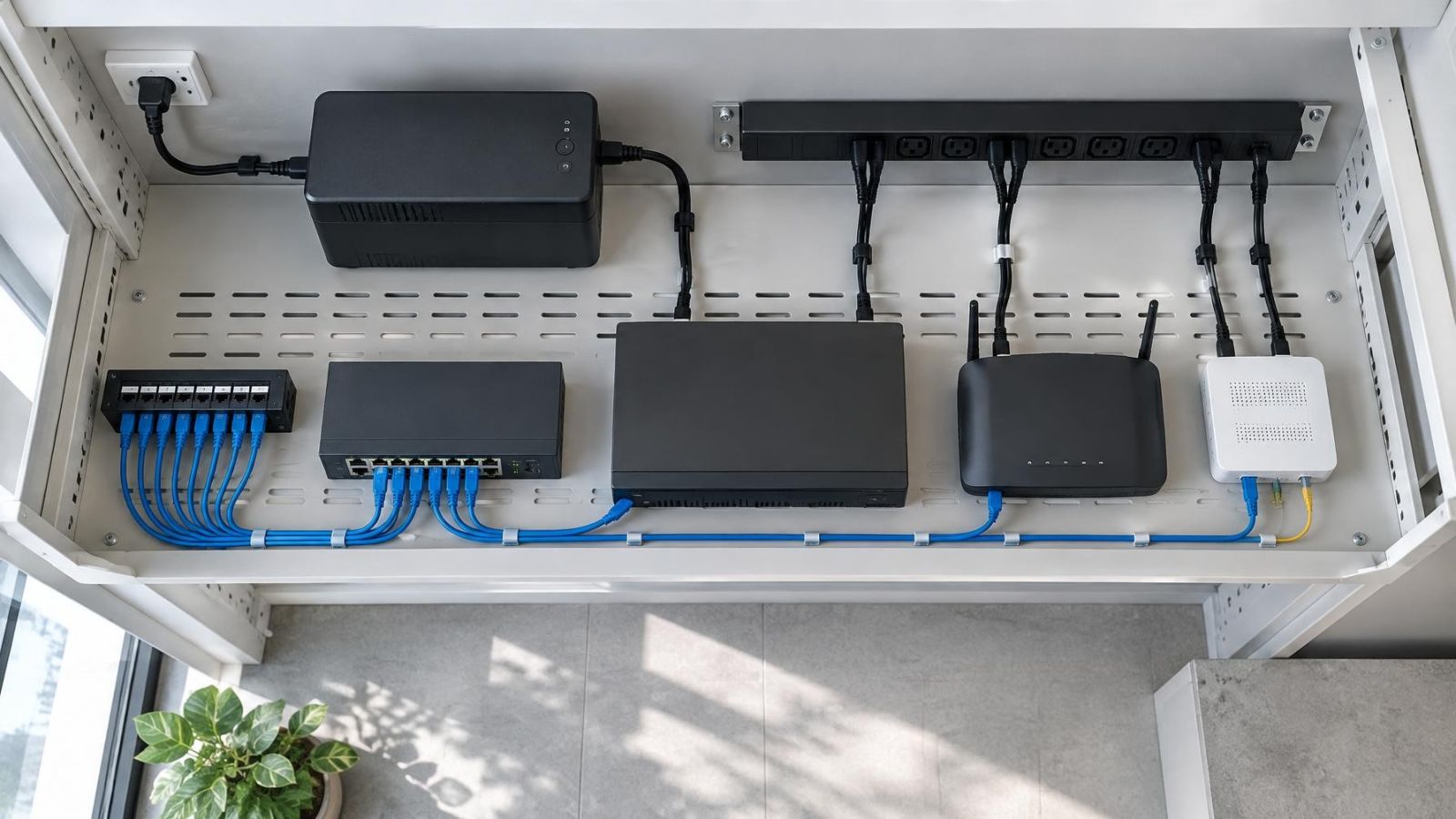
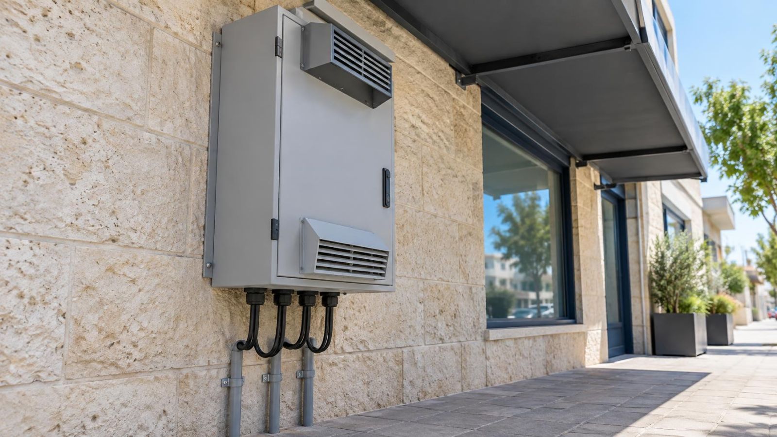
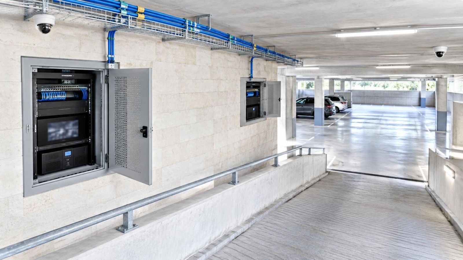
Camera switches should sit in protected, ventilated and serviceable locations. The best position is not simply the geometric centre of the cameras. Cable lengths matter, but so do heat, dust, moisture, physical access and the route of the uplink back to the recorder.
| Layout | Main advantage | Main dependency | Best fit |
|---|---|---|---|
| Centralised switching | Fewer equipment locations and simpler routine maintenance | One switch or cabinet may serve many cameras | Compact apartments, small offices and sites with practical cable routes |
| Distributed switching | Shorter local camera runs and smaller switch fault zones | Each remote switch depends on its power and uplink | Private homes with gardens, divided premises and shops with separate front and rear areas |
In an apartment, a central cabinet may be the cleanest arrangement, especially when all cables return through the apartment rather than shared building spaces. A camera at a shared entrance may depend on building-wide infrastructure or a va'ad bayit decision, so it should not be treated as if it were simply another room connection.
A private home may justify a remote switch serving a gate, parking area or garden structure. This shortens several camera cable runs, but the remote switch needs a suitable enclosure, ventilation, reliable power and a protected uplink. In a street-front shop, keeping public-facing cable routes away from easy interference is often more important than saving a few metres of cable.
Accessibility is part of reliability. A switch should not be buried behind fixed shelving or placed where routine diagnosis requires disturbing unrelated equipment. At the same time, it should not be exposed to casual handling. Coastal humidity, airborne dust and heat inside closed cabinets all deserve attention when choosing the location.
Divide Failures Into Smaller Zones
Distributed switching can limit the area affected by a switch failure, but only when the groups are chosen deliberately. Grouping every external camera on one switch may look tidy, yet it can remove all external views together. A better arrangement may divide cameras by area, function or priority.
When is camera network redundancy useful?
Camera network redundancy is useful when losing one shared component would remove several important views or stop access to the normal recording path. Redundancy does not always mean duplicating the complete system. It may mean placing two priority cameras on different switches, using separate cable routes, or providing independent uplinks where the site and operational need justify them.
Consider a home with a vehicle gate and a pedestrian entrance. If both views are important, connecting them through different fault domains can preserve one view when a local switch or cable route is unavailable. In a shop, the entrance overview and payment-area view may be more useful on different switch groups than two cameras covering the same aisle.
- Group cameras by the consequence of losing them together, not only by physical proximity.
- Place complementary priority views on different switches or uplinks where practical.
- Use independent uplinks only when they are genuinely independent along the relevant route.
- Keep spare switch ports for diagnosis, replacement and carefully planned expansion.
- Label both ends of every camera cable, each switch port, every uplink and each relevant power feed.
Labelling is not cosmetic. Clear labels make cable, port and power faults easier to isolate. The label should identify the camera location in language that remains obvious to someone who did not install it. Names such as “rear garden gate” or “shop front left” are more useful than an unexplained sequence.
Plan Power Alongside Data
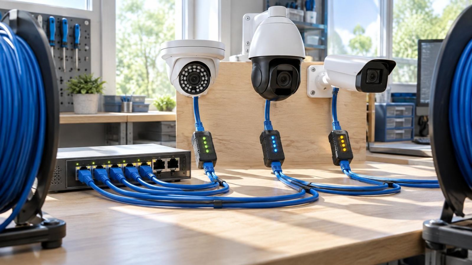
PoE combines data and camera power on the network cable, but it does not remove power planning. Each switch has a total PoE capacity, and each connected camera places demand on it. Cameras may draw differently when IR illuminators, heaters or other functions operate. Capacity should be checked for the intended operating condition, not merely for a camera sitting idle during installation.
Trace the power path for the switches, recorder, router, local monitor and any link equipment. Backup power only supports equipment connected to the backed-up power path. Backing up the recorder but not the camera switches leaves the recorder running without incoming camera traffic. Backing up switches and the recorder but not the router may preserve local recording while remote access remains unavailable.
Restart behaviour also matters. After an interruption, network equipment may return in a different order. Cameras can start before their switch uplink is ready, or the recorder can start before all cameras become reachable. The system should be checked after a complete power cycle so that delayed reconnection, incorrect time settings or devices requiring manual attention are discovered during commissioning.
What Happens When a Switch Fails?
When a camera switch fails, the cameras connected through it become unreachable from the rest of the network. Their feeds normally stop arriving at the NVR, creating recording gaps for that group. Cameras on other functioning switches can remain available if their own paths to the recorder are intact.
The visible symptom does not identify the failed component by itself. Several missing cameras may indicate a switch fault, loss of switch power, a damaged uplink or an upstream network problem. If only remote viewing is unavailable, the internet connection or router may be the issue while the local camera network continues to operate.
- List the unavailable cameras and check whether they share one switch, cabinet or uplink.
- Check whether the affected switch has power and whether its normal status indicators are present.
- Test local viewing at the recorder or a local workstation before treating the issue as an internet failure.
- Check the uplink between the affected switch and the rest of the network.
- Confirm whether unaffected camera groups are still recording.
- Use the cable and port labels to isolate one path at a time rather than moving several connections together.
A fault is easier to diagnose when the topology predicts exactly which cameras should disappear together.
Local recording can continue without internet when the cameras and recorder remain connected on the local network. The internet is generally needed for remote access, not for traffic travelling between local cameras and a local NVR. Cloud-dependent functions are a separate path and should not be confused with the recorder's local operation.
Choose the Topology Before Cabling
The topology should be decided before cable routes are closed and cabinets are filled. Begin with the failures the property needs to tolerate. A remote owner may place greater value on keeping local recording active during an internet interruption. A shop may prioritise keeping its entrance and operational areas on separate switch groups. A private home may need a practical boundary between the main building and equipment serving the gate or garden.
Choose centralised or distributed switching from that requirement, not from habit. Then reserve suitable cable routes, spare ports and cabinet space. If a second uplink may be useful, it needs a genuinely separate path to offer meaningful independence. Two cables placed together through the same vulnerable conduit still share a physical failure point.
Separating camera traffic from general network traffic can simplify diagnosis and traffic management. This may use physically separate switching or a VLAN (virtual local area network), depending on the size and administration of the network. Separation does not replace bandwidth planning, secure configuration or clear documentation. It simply gives camera traffic a defined place in the network.
Finish with a topology diagram that matches the installed system. It should show camera names, cable identifiers, switch ports, uplinks, recorder connections, network separation and power backup boundaries. Keep a copy where it is available to the people responsible for the property, including a remote owner or business manager. A simple, accurate diagram is more useful than a detailed document that no longer matches the equipment.
Key takeaways
- Every shared switch, uplink, recorder and power source should be mapped before equipment locations are chosen.
- Important views should be distributed so one equipment fault does not disconnect every camera covering the same priority area.
- Power backup is part of the network topology because it supports only the equipment connected to its backed-up path.
- Local recording can continue without internet access when the cameras and recorder remain connected on the local network.
- Clear labels for cables, ports, uplinks and power feeds make faults easier to isolate.