On this page
When IP cameras, PoE (power over Ethernet) switches, a network cabinet and an NVR (network video recorder) must work together, the physical layout matters as much as the equipment list. Ethernet and fibre uplinks determine how camera traffic reaches the recorder, while an uninterruptible power supply determines which parts continue operating during a power interruption. The central question settled here is which CCTV switch topology fits the property: one central switch, several local switches, or a combination of both.
How the two topologies differ
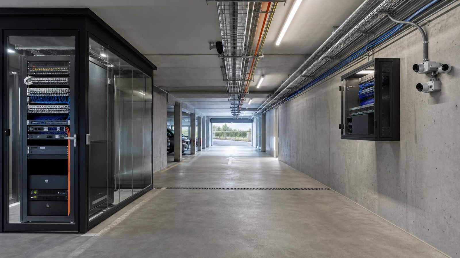
A centralised topology gives every security camera its own Ethernet run back to a shared switch location. The PoE switches, core network equipment, NVR and backup power can all sit in or beside one network cabinet. This is often easy to understand and service. It also demands suitable cable routes from every camera position to that cabinet.
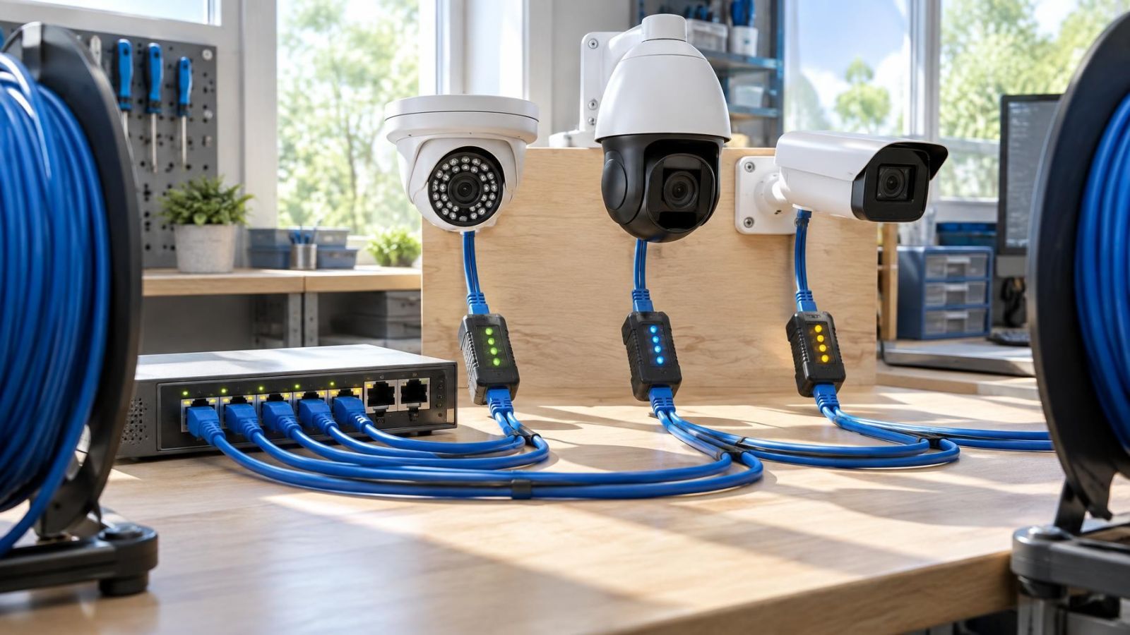
A distributed topology places smaller PoE switches near groups of cameras. One switch might serve a gate and garden, while another serves cameras around a detached office or the far end of commercial premises. Each local switch sends the combined camera traffic towards the recorder network over a switch uplink.
| Layout | Camera cabling | Uplinks | Powered locations |
|---|---|---|---|
| Centralised | Home runs to one cabinet | Mainly inside the cabinet | Usually one main location |
| Distributed | Shorter runs to local switches | One uplink from each camera group | Several locations |
| Hybrid | Home runs locally within each area | Central and remote links combined | Main cabinet plus selected remote points |
Hybrid layouts are common in properties that do not behave like one compact building. The main structure may use home-run cabling, while a gate, garden room, warehouse area or separate floor has a local switch. Hybrid should be a planned topology, not a collection of switches added wherever a cable happened to stop.
Which CCTV switch topology fits: centralised or distributed?
Start with the shape of the property. A compact apartment, office or shop with usable ceiling routes usually favours central switching. A private home with a deep garden, a remote gate or several structures may produce cleaner routes with local switching. Larger premises are not automatically distributed; accessible ducts and a well-positioned cabinet can make home runs practical over a broad area.
When is a centralized PoE switch the better fit?
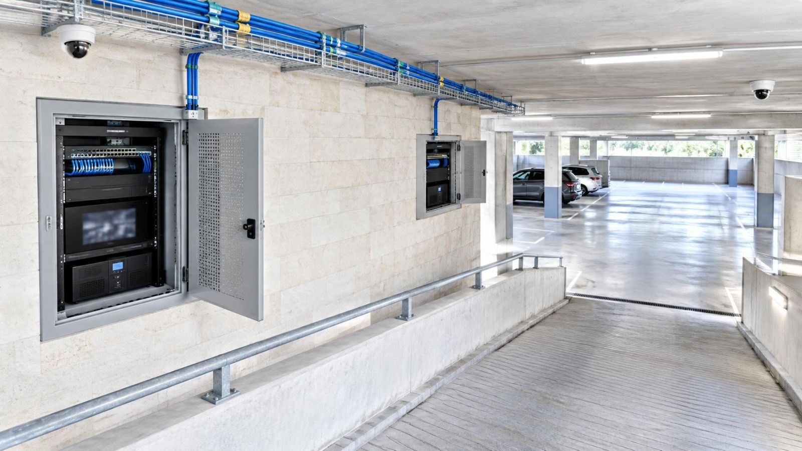
A centralized PoE switch is the better fit when camera cables can reach one dry, accessible cabinet without awkward detours. It keeps backup power, heat management, port status and troubleshooting together. Remote property owners may also value having fewer equipment locations that someone must physically inspect.
When do distributed PoE switches make sense?
Distributed PoE switches make sense when cameras form clear physical groups and the routes back to the main cabinet are difficult, congested or unnecessarily long. They can also create useful failure boundaries: a fault in one remote switch affects its local group rather than every camera. The trade-off is more enclosures, power connections and access points to maintain.
Cabinet locations matter as much as distance. A convenient point on a drawing may be unsuitable if it is locked by another tenant, exposed to sun, used for storage or inaccessible outside business hours. Decide how much shared failure is acceptable as well. One central switch is simple, but it can become a single point of failure for every camera attached to it.
Compare cabling and uplink demands
In a centralised layout, count and route one Ethernet cable from every camera position to the main switch. Check the complete path, not only the straight-line distance. Ceiling changes, reinforced walls, service shafts, garden trenches and the route around a mamad can turn a nearby camera into a difficult cable run.
In a distributed layout, camera cables terminate at the local switch. The uplink then carries the aggregate traffic produced by all cameras on that switch. PoE capacity does not tell you whether the uplink is suitable; power delivery and network traffic are different parts of the design. Expected recording modes, live viewing and simultaneous playback should be considered when selecting the uplink.
Fibre is often useful between separate buildings or over remote outdoor routes. It supports long links and does not create a conductive data connection between the two ends. It still needs compatible network equipment, a protected route and power at the remote switch. Fibre does not remove the need to plan the local enclosure or backup supply.
- At a gate, identify where the local switch, fibre termination and power equipment will remain dry and serviceable.
- In a garden, plan the route around irrigation, soil movement and maintenance work rather than relying on the shortest line.
- At street-frontage premises, keep uplink and camera routes away from shutters, signs and fittings that may later be replaced.
- Where several remote switches share an upstream link, calculate the combined traffic beyond the first aggregation point.
Plan power, backup and cooling
A PoE power budget is based on what the connected cameras may require in operation, not simply on the number of ports. IR illuminators for night vision, motorised movement and other powered features can change demand. The switch needs enough available PoE power for the planned cameras, with sensible capacity for replacement units or later additions.
Distributed designs repeat this calculation at every switch. Spare ports are useful only if the switch also has power available for the devices connected to them. A main switch with generous capacity cannot compensate for an overloaded remote switch.
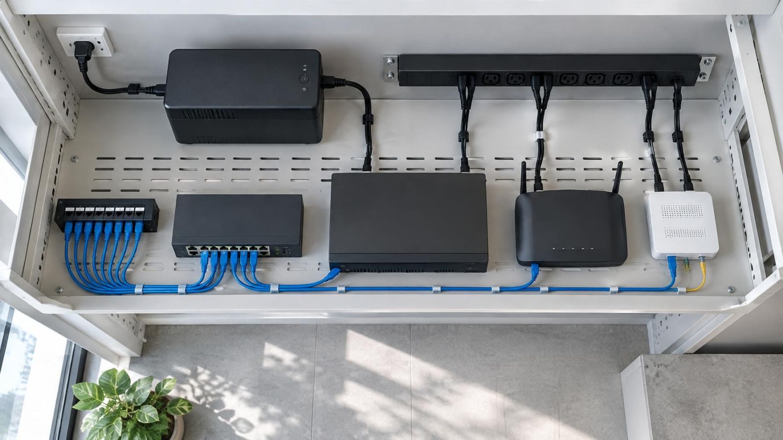
Backup power has the same boundary. An uninterruptible power supply supports only the switches, uplinks, recorder and related network equipment connected to it. If the main cabinet is backed up but a remote PoE switch is not, the cameras on that switch stop operating when its local power is interrupted. Every active point along the recording path must be considered.
Cooling is not an optional cabinet detail. Switches and power equipment release heat, and a closed enclosure in direct Israeli sunlight can become unsuitable even when the surrounding air feels reasonable. Dust can obstruct airflow. Near the coast, humidity and contaminated air make exposed connectors and unsuitable enclosures a poor long-term choice.
- Confirm the operating power demand of each camera and assign it to a specific switch.
- Keep capacity for realistic camera changes, not merely unused port numbers.
- List which switches, uplink devices and recording equipment are covered by each backup supply.
- Provide ventilation appropriate to the environment without exposing equipment directly to dust, moisture or sunlight.
- Avoid filling a cabinet so tightly that air cannot move around powered equipment.
Where should PoE switches be placed?
Place a PoE switch in a dry, ventilated and serviceable location with controlled access. A proper network cabinet is preferable to a shelf above a ceiling tile or an outdoor box selected only because it was easy to mount. Installers need room to see indicators, test ports, trace cables and replace equipment without disturbing unrelated electrical or communications systems.
For distributed switching, the best position is not always the geometric centre of the camera group. A slightly longer camera run may be worthwhile if it moves the switch indoors, out of direct sunlight and into a place that can be reached without ladders, keys from several people or interruption to business activity.
In an apartment building, corridors, roof spaces, parking areas and shared entrance cabinets may be managed as common areas. Coordination with the va'ad bayit is a practical part of the design because access, cabinet use, cable routes and future servicing can affect other residents. Establish who can open each location and how an installer will reach it later.
A mamad is also relevant to routing. Its reinforced walls can make a route that looks simple on a floor plan difficult in practice. Use existing practical paths where possible, and decide cable entries before finishing cabinetry or decoration. Do not choose wireless links merely to avoid planning a difficult wall route; first assess whether a dependable wired path is available.
Understand maintenance and failure boundaries
A central switch fault can affect every camera connected to that switch. Centralisation makes the fault broad, but diagnosis is usually straightforward because camera cables, switch ports, backup power and the recorder network are together. A technician can compare ports and test individual runs from one cabinet.
A remote switch fault normally affects the camera group behind that switch. The same local group can also disappear because of an uplink fault, local power interruption or enclosure problem. This narrower failure boundary is useful, but only if the remote location is identifiable and accessible.
Distributed equipment adds routine work. Someone must be able to reach each enclosure, inspect its power source and distinguish the uplink from camera ports. A switch hidden above a shop ceiling or behind stored items may save cable during installation while making every later visit slower.
- Label both ends of every camera cable with a stable camera identifier.
- Label each uplink by its destination, not merely as uplink.
- Record which backup supply serves each switch and intermediate uplink device.
- Keep cabinet and enclosure names consistent across labels, drawings and the VMS (video management software).
- Document unused ports and cables rather than leaving their purpose to guesswork.
Choose and document the topology
Make the final choice only after the camera positions and real cable paths are known. A tidy conceptual diagram is not enough if the proposed cabinet has no ventilation or the gate uplink has no protected route. Walk the property where possible, or obtain clear plans and photographs when managing it remotely.
What belongs in a camera network design?
A camera network design should show each camera, its serving switch, the switch location and the path towards the NVR. It should also record the uplink medium, PoE demand, expected aggregate traffic and backup power boundary. For a managed network, note the relevant VLAN and which device provides routing or controlled access between network segments.
- Assign every planned camera to a named switch and port range.
- Prepare a power schedule showing camera demand and available PoE capacity at each switch.
- Record the expected camera traffic on every local and shared uplink.
- Specify Ethernet or fibre for each link and identify all active equipment required at both ends.
- Mark which switches, uplinks and recording devices receive backup power.
- Produce an installer-ready topology drawing with cabinet names, enclosure locations, cable identifiers and uplink destinations.
Documentation is especially valuable in a hybrid layout because the system may look centralised from the recorder while depending on several remote switches. A clear drawing prevents a later installer from treating an uplink as a camera cable, overlooking a local power dependency or adding a camera to a switch that lacks usable PoE capacity.
The best topology is the one whose cable routes, power boundaries and service locations remain understandable after the installation is finished.
Key takeaways
- Centralised switching simplifies backup power and maintenance but requires a separate cable route from each camera to the main cabinet.
- Distributed switching shortens camera cable routes but creates additional powered locations that need protection, access and maintenance.
- PoE power demand and uplink traffic are separate calculations, and both need capacity for later changes.
- Heat, dust, coastal humidity and reinforced walls can determine which switch locations are practical in an Israeli property.
- A hybrid topology often provides the cleanest design when a property has distinct camera clusters around a gate, garden, outbuilding or street frontage.