On this page
IP cameras are connected to a PoE switch, the network recorder is running, and the Ethernet cabling appears secure inside the communications cabinet. Then every camera disappears at once. Even a managed switch may become difficult to access. The cause can be one extra cable creating a circular Ethernet path. This article explains why that network loop can overwhelm the whole camera system, how to identify it without losing track of the cabling, and how to reduce the chance of it returning.
What Is a Network Loop?
A network loop is a circular path between switch ports. Traffic leaves one port, passes through one or more switches, and returns to a point it has already crossed. The switches may then forward the same traffic again. Instead of reaching a destination and ending, some frames continue travelling around the loop.
The simplest loop is a single Ethernet cable connected between two ports on the same switch. A more common and less obvious version involves linked switches. One uplink already connects switch A to switch B, and a second cable creates another path between them. A loop can also pass through a home router, a small office switch or equipment serving a shared building entrance.
Not every repeated connection is necessarily a fault. Some networks are deliberately designed with more than one physical path and use managed controls to keep only a safe forwarding path active. The problem begins when parallel paths are added without the switches being configured to manage them.
Accidental return paths often appear during ordinary cabling work. Someone reconnects both ends of an unidentified spare cable, adds a temporary switch, or links the camera network to the general network in a second place. Each connection can look reasonable when viewed on its own. The circular path becomes visible only when the complete topology is considered.
Why Every Camera Can Disappear
A loop does not need to pass through every camera port to affect every camera. Broadcast and other flooded traffic can be copied repeatedly as it travels around the circular path. This multiplication is often called a broadcast storm. It consumes switch capacity and can occupy the links that normally carry video.
Camera streams compete with the repeated traffic. The NVR (network video recorder) may lose its sessions with several or all cameras. Live view becomes intermittent, recordings develop gaps, and attempts to open the recorder or switch interface may become very slow. The management tools needed to diagnose the problem can therefore be affected by the same fault.
The mistaken cable might be attached to an access switch in one part of the building while the unavailable cameras are connected to a different switch. They still share an uplink, recorder or switching path. This is why investigating each camera individually can waste time when many channels fail together.
Can powered cameras still be offline?
Yes. PoE (power over Ethernet) and network communication are related, but they are not the same function. A switch may continue supplying electrical power while useful traffic is crowded out. Camera status lights or infrared illumination may remain visible even though the recorder cannot receive video.
Power confirms that a camera is receiving electricity. It does not confirm that the camera, recorder and viewing device can communicate.
A camera network outage with powered devices is therefore consistent with a switching problem. Rebooting cameras may briefly change what appears on screen, but it does not remove the circular cable path. The physical and logical topology still needs attention.
Recognising Ethernet Loop Symptoms
The most useful clue is the pattern of failure. One unavailable camera can point to its cable, PoE port, configuration or the camera itself. Several cameras disappearing together suggest a shared component or shared network path. A loop is one possible cause, alongside an uplink failure, switch problem or recorder-side issue.
What are the usual Ethernet loop symptoms?
- Several cameras drop at roughly the same time, including cameras connected to different access ports.
- Live video appears briefly, freezes and returns, while recording shows corresponding gaps.
- Many switch-port activity lights flash rapidly even when there is little expected user activity.
- The recorder interface, managed-switch interface or general network access becomes unusually slow.
- Service improves soon after one particular uplink or patch cable is removed.
- Cameras remain powered, but video and management access are unavailable.
No single symptom proves that a loop exists. Rapid activity lights can also represent legitimate camera traffic, especially on an uplink carrying many streams. Recording gaps can have other causes. The stronger indication is a group of symptoms that begins or ends when a particular network path is connected or removed.
Be careful with temporary recovery. If pulling a cable restores the cameras, that cable may form one side of the loop without being defective. Replacing it with a new cable in the same two ports recreates the topology and may recreate the outage. Record the port at each end before moving anything else.
Where Camera-System Loops Begin
Parallel uplinks are a frequent starting point. A main switch and a remote PoE switch are already linked, but a second uplink is added because the first connection was forgotten or poorly labelled. Unless the network is intentionally configured for redundant paths, both links can create a loop.
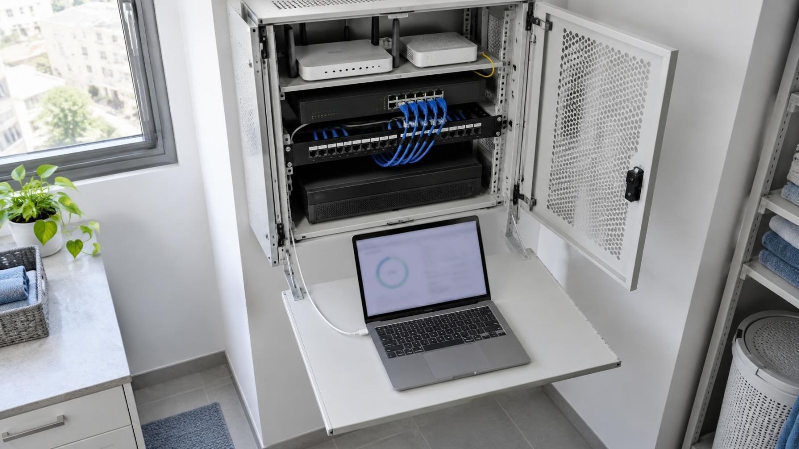
Spare cables create another risk. Inside a crowded communications cabinet, both ends may look unused. Connecting them to convenient empty ports can join two switches that are already connected elsewhere. Patch leads running behind equipment make the full path particularly difficult to see.
A camera network can also be joined to the home or business network twice. For example, the NVR side may already have a connection to the router, while an access switch is connected to the same network through another route. Whether that arrangement creates a loop depends on the recorder design and port configuration, so assumptions based only on socket labels are unsafe.
Israeli apartment buildings often place several services in or near shared communications areas. A connection for entrance cameras, an apartment network or another shared device may be added without a current diagram of the existing links. Changes involving shared equipment should be reviewed as part of the whole topology, not as an isolated patch.
In private homes, loops can appear when a garden office, gate, wireless access point or distant camera switch has both a permanent uplink and a temporary return cable. In a street-front business, a small switch added near a counter or back office may quietly create the second route. The equipment does not need to be inside the main cabinet to affect the camera system.
How Can I Detect a Loop in My Network?
Start by treating the network as a topology rather than a pile of cables. The aim is to identify which connection completes the circle while preserving enough information to rebuild the intended network. Methodical fault isolation is slower than random unplugging for the first few minutes and much faster when the system must be restored correctly.
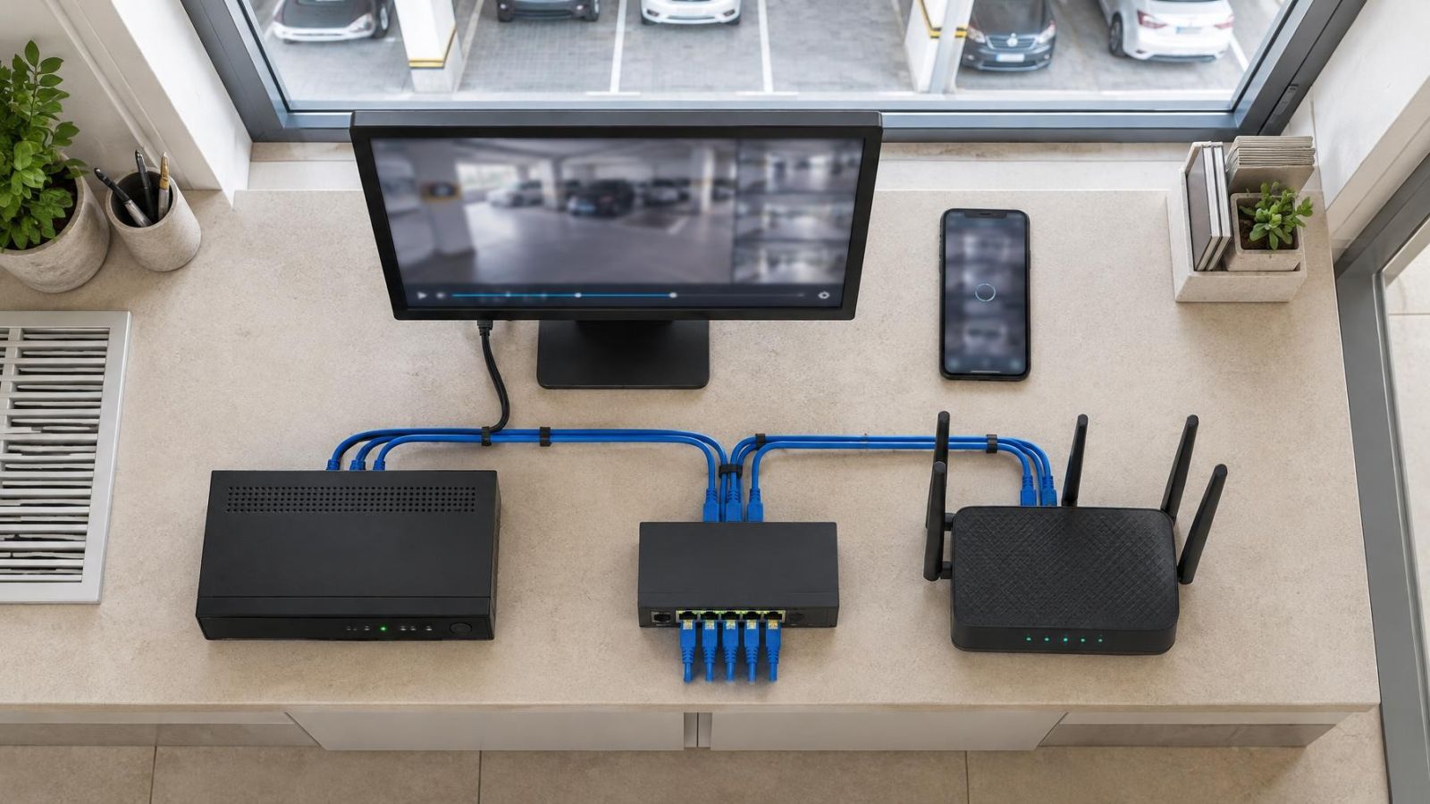
- Sketch the current topology. Mark the router or firewall, recorder, main switch, PoE switches, uplinks and any connection to shared-building equipment. Photographing the cabinet can supplement the sketch, but it may not show where remote cable ends terminate.
- Record active ports. Note each connected port and its label before removing cables. If a managed switch remains accessible, save or write down useful port status and loop-related log information.
- Separate the recorder and camera network from the wider network. Disconnect only the intended external uplink, then observe whether local camera communication becomes stable. This helps distinguish an internal camera-network loop from a path involving the general network.
- Remove switch uplinks methodically. Change one connection at a time. Allow the switches and recorder time to resume normal communication before judging the result.
- Build a known-good minimal network. Keep the recorder, one switch and a small camera branch connected. Confirm that management access and video remain stable before adding another branch.
- Restore branches individually. Reconnect one documented cable, observe the network, and record the result. If instability returns, leave that cable disconnected until both endpoints and the complete path are understood.
- Review the final topology. Do not reconnect a cable merely because the system recovered after its removal. Determine whether it is unnecessary, incorrectly patched or intended to be controlled by switch configuration.
Managed-switch information can narrow the search. Port counters, changing link status, learned device addresses and loop alerts may indicate where traffic is circulating. However, a heavily affected switch may respond slowly or not at all. Physical isolation remains important when management access is unreliable.
Remote property owners need someone on site who can identify ports precisely and report each change. Instructions such as “remove the blue cable” are unsafe when several cables look alike. Use cabinet labels, switch names and port identifiers, and ask for confirmation before the next step.
Restoring Service Without Creating Confusion
Once the suspected loop path is open, restore service from a known-good minimum. Connect the recorder to the required camera switch, verify local communication, and add the remaining network branches one at a time. A stable result after each change makes the next result meaningful.
Is there a safe switching loop fix?
The safe fix is to remove the unintended circular path and then confirm the intended topology before reconnecting anything. Leave the suspect cable disconnected and labelled while tracing both ends. If the second path is required for a deliberate network design, it needs appropriate managed-switch configuration rather than an informal patch between ports.
Keep configuration changes separate from physical testing where possible. Resetting the recorder, cameras and switches at the same time removes useful evidence and introduces new variables. A cabling loop generally does not require camera settings to be erased. Preserve configurations unless there is a separate, identified reason to change them.
Also separate power observations from reachability tests. A lit PoE port shows that power negotiation may be active. It does not establish that video reaches the recorder. Confirm live view, recording, camera management access and switch access rather than relying on indicator lights alone.
Choose Safeguards and Document the Network
Managed switches can detect or block some loop conditions, depending on their features and configuration. Loop protection can limit disruption, but it should not be treated as permission to create uncertain parallel paths. Protection settings need to match the intended topology, and alerts need to remain visible to whoever maintains the network.
| Safeguard | What it contributes | What it does not replace |
|---|---|---|
| Managed-switch loop protection | Can block or limit an unintended forwarding path | A clear understanding of which switches should be linked |
| Cable and port labels | Identify camera runs, uplinks and remote switch connections | Testing when cable endpoints remain uncertain |
| Network diagram | Shows how the router, recorder and switches are intended to connect | Updating the record after physical changes |
| Controlled unused ports | Reduces casual or accidental patching | Responsible management of authorised changes |
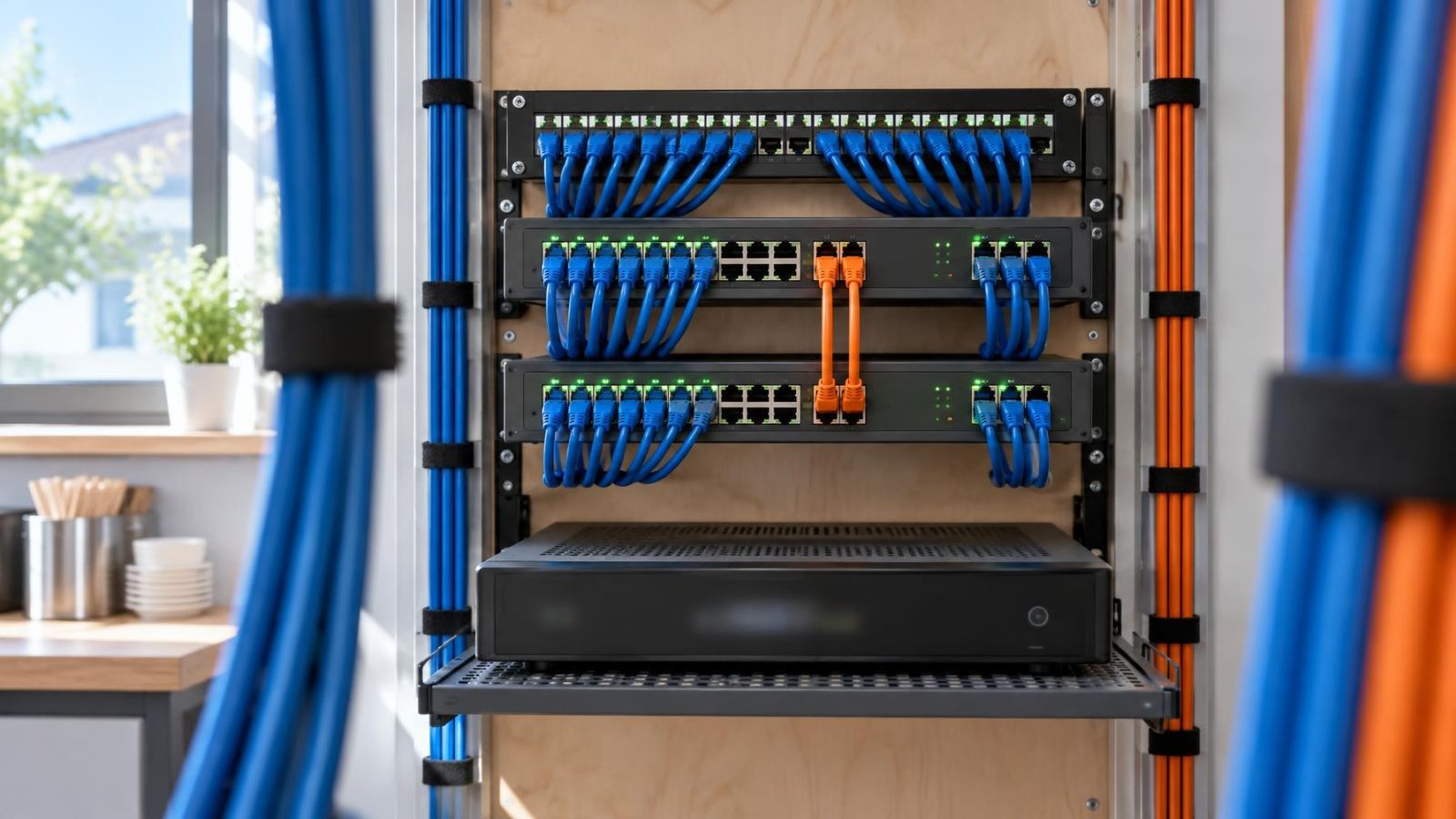
Labels should describe function, not only location. “Uplink to gate switch” is more useful than “cable 4”. At both ends, identify the connected switch and port where practical. Camera runs should be distinguishable from switch uplinks, recorder links and connections to the general network.
Place a simple diagram near the communications cabinet and keep another copy where it can be retrieved if cabinet access is difficult. The diagram does not need specialist symbols. Boxes for devices and lines for cables are enough, provided remote switches and external network connections are included.
Unused switch ports should not become convenient sockets for unreviewed connections. Assign responsibility for access-switch changes to a person who will check the diagram and update it afterwards. In an apartment building, that may require coordination between the apartment owner, the person handling shared-building systems and the installer. In a small business, it may simply mean that temporary equipment is not patched into the camera cabinet without recording the change.
Recurring simultaneous outages deserve an installer review even when unplugging one cable appears to restore service. The disconnected path may reveal an undocumented switch, a duplicate uplink or a wider design problem. A stable camera network is not only a collection of working devices. It is a clear topology in which every connection has a known purpose.
Key takeaways
- A single incorrect cable connection can disrupt cameras across the network, including cameras far from the mistaken cable.
- A camera receiving PoE can remain powered while its video stream is completely unreachable.
- Simultaneous camera failures usually justify checking shared switches and uplinks before investigating individual cameras.
- Methodical cable isolation is more reliable than disconnecting several cables without recording each change.
- Loop protection is most effective when supported by labelled cabling and an accurate network diagram.