On this page
Open a communications cabinet and the network path may look simple: a power over Ethernet (PoE) switch connects each IP camera by Ethernet cable, while a gigabit uplink connects the switch to an NVR (network video recorder). In practice, PoE switch uplink bandwidth matters more than the speed printed beside each camera port. The question settled here is where combined camera traffic accumulates, how to find the real bottleneck, and how to choose a balanced switch for an Israeli home or small business.
PoE Switch Uplink Bandwidth: Camera Traffic and Network Paths
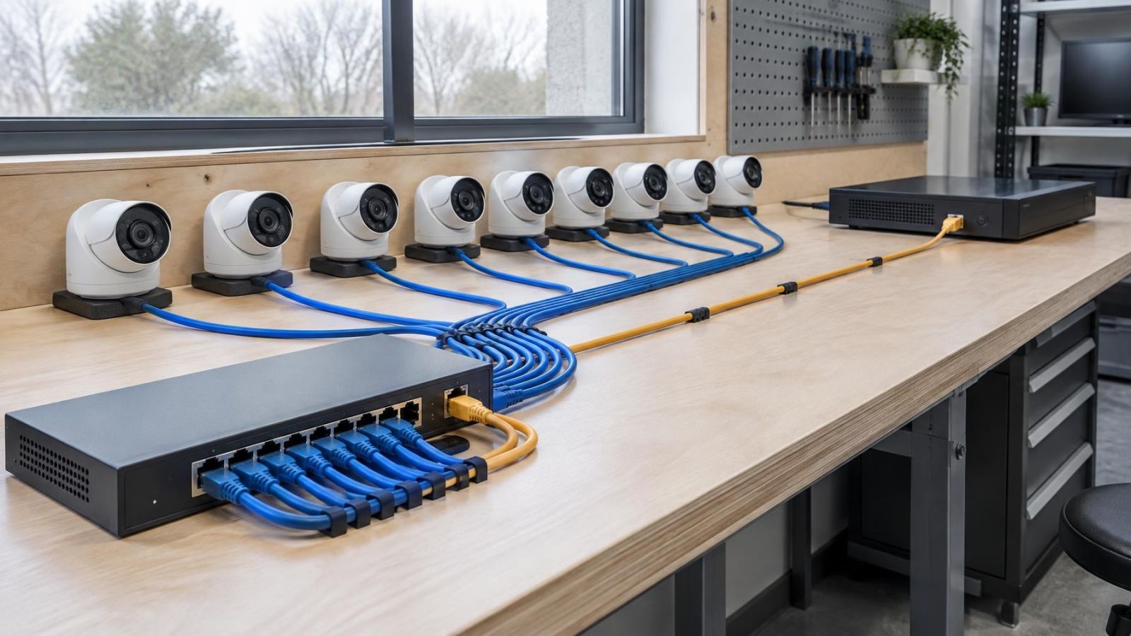
An individual switch port normally carries traffic for the camera connected to it. The uplink has a different job. It may carry video from every camera on that switch toward the recorder, along with management traffic, audio where enabled and requests from viewing devices. The relevant load is therefore not one camera’s bitrate. It is the combined traffic crossing the shared link.
What does a camera switch uplink carry?
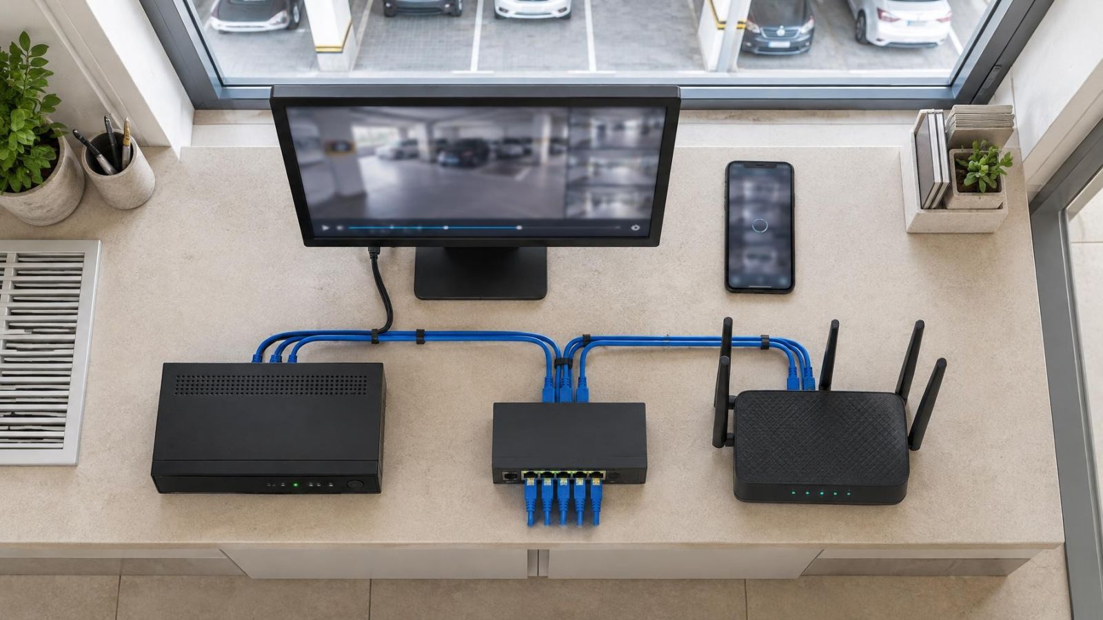
Start by drawing the actual path. A camera sends its stream into an access port. The switch forwards it through an uplink, possibly through another switch, and finally into the NVR. If several camera switches are cascaded, each link closer to the recorder carries more combined traffic than the links farther away.
Local and remote viewing also need to be placed on that drawing. A monitor connected directly to the recorder may add no camera-network traffic. A computer running VMS (video management software) can receive video across the network. Remote access usually causes the recorder or camera to send an additional stream through the router. Whether that traffic crosses the camera switch depends on the topology.
Bitrate is not perfectly fixed. It changes with the number of pixels per frame, frame rate, compression settings, scene activity and the streams that are enabled. Trees moving in strong sunlight can produce a different load from a quiet indoor corridor. Network protocols also add traffic overhead. Planning from a single favourable bitrate reading gives a false sense of precision.
Why Is Camera Port Speed Secondary?
A camera port’s stated speed is an upper limit for that Ethernet connection. It does not describe the camera’s normal video demand. A single compressed stream generally uses far less capacity than the port can carry, so making the access port faster does not automatically improve recording or image quality.
The actual traffic is driven by camera configuration. More pixels per frame, a higher frame rate, less aggressive compression and a busy scene can all increase bitrate. Audio, metadata and an additional stream for live viewing add further traffic. Those settings matter more than the access port label when estimating load.
The distinction becomes important when comparing switches. Fast camera ports paired with a constrained uplink can still concentrate all video onto the slower shared connection. Conversely, ordinary camera ports can be entirely suitable when each camera’s demand remains comfortably below the port limit and the uplink has room for the aggregate load.
Does camera port speed affect image quality?
Port speed does not set image quality by itself. It determines how much data the link can carry. Image settings determine the stream, while the network must carry that stream without sustained congestion or link errors. If the path is constrained, symptoms may include delayed live view, interrupted playback or missing recording intervals, but a higher port rating alone does not identify the cure.
Where Does the Bottleneck Form?
The most obvious bottleneck is the switch uplink because it combines many camera streams. It is not the only candidate. The recorder’s network interface can be constrained, and the recorder may have a separate limit for incoming recording traffic. A fast switch cannot make the recorder ingest more video than its own interface and processing path can accept.
Cascaded switches require particular care. Suppose an outer gate switch connects to a garden switch, which then connects to the main cabinet. Traffic from both remote groups crosses the final link to the recorder. Adding cameras at the edge therefore increases the load on every shared link upstream, not only on the nearest switch.
General network traffic may share the same path. Computers copying files, wireless access points, internet traffic and remote backups can compete with video when everything uses one uplink. A dedicated physical path or a correctly designed VLAN can make traffic easier to understand, but separation does not create bandwidth. Shared interfaces still need sufficient capacity.
Cable condition matters as much as the labels on the equipment. Poor terminations, damaged cable, unsuitable joins or excessive exposure can cause a link to negotiate below its intended speed or generate transmission errors. A gigabit uplink that is operating on a poor Ethernet link is not functioning as the plan assumes.
- Check the negotiated link speed at both ends of every shared connection.
- Inspect patch leads, plugs, sockets and field terminations rather than replacing the switch first.
- Include intermediate switches and router connections in the path drawing.
- Compare the recorder’s network interface and ingestion capacity with the total planned camera traffic.
Uplink Speed Versus Switching Capacity
Uplink speed and internal switching capacity describe different parts of a switch. Uplink speed is the rate available on a particular interface. Switching capacity describes how much traffic the switch can move internally across its ports. A switch needs both an appropriate uplink and enough internal capacity to handle simultaneous traffic.
Ethernet links are normally full duplex, meaning they can send and receive at the same time. Specification sheets may present switching figures as combined traffic in both directions. Camera networks are usually dominated by traffic travelling from cameras toward the recorder, so an impressive bidirectional total should not be mistaken for unlimited capacity in the direction that matters.
What does “gigabit CCTV uplink” mean on a specification?
The phrase usually refers to a gigabit-capable uplink intended to aggregate security-camera traffic. It does not guarantee that every part of the switch, recorder and cable path can sustain the same load. Check whether the quoted figure refers to a physical uplink, total switching capacity, packet-forwarding performance or a marketing description of the product’s intended use.
| Specification | What it describes | What it does not establish |
|---|---|---|
| Camera port speed | Maximum link rate for one connected camera | Combined traffic from the switch |
| Uplink speed | Maximum link rate on the shared uplink interface | Recorder ingestion capacity |
| Switching capacity | Internal ability to move traffic among ports | Available PoE power |
| PoE power budget | Electrical power available to connected devices | Video bandwidth |
| Recorder capacity | Traffic the recorder can accept and process | Condition of the Ethernet path |
Bandwidth and Power Need Separate Checks
PoE combines power and network data on the same cable, but the two budgets remain independent. A switch can have enough electrical capacity for all connected cameras while lacking a suitable uplink. It can also have ample network capacity while running short of power when IR illuminators, motorised mechanisms or other high-load features operate.
Calculate aggregate bandwidth from the streams that will actually cross each shared link. For every camera, include the recording stream and any additional stream that regularly follows the same path. Add protocol overhead and operating headroom rather than treating the calculated total as a target to fill completely.
The practical calculation is aggregate traffic = sum of camera stream bitrates + additional regular traffic + headroom. Repeat it for each uplink because different links collect different groups of cameras. Use configured or conservatively estimated bitrates, not the speed printed beside the camera’s Ethernet port.
Then perform a separate power calculation. Consider each camera’s expected operating load, including IR at night and any powered accessories. Compare the total with the switch’s PoE budget and with any per-port power limits. A total power figure cannot reveal whether one particular port can supply a demanding device.
Finally, check the NVR. Its network interface, supported incoming bitrate, recording configuration and live-view workload all belong in the same plan. A fast uplink cannot compensate for a recorder interface or ingestion path that is already constrained.
A balanced camera network has enough capacity at every shared link, enough power at every PoE port and enough ingestion capacity at the recorder.
Planning for Israeli Properties
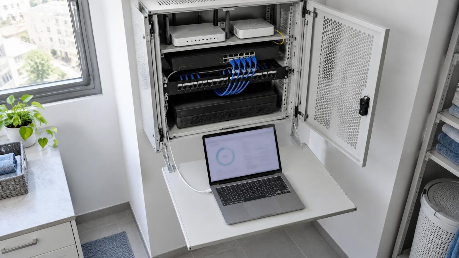
Israeli apartment communication cabinets are often compact and already contain the router, fibre equipment, patching and household network hardware. Port count is only one concern. The switch must fit with sensible cable bends, accessible connectors and ventilation. Packing active equipment tightly into an enclosed cabinet makes inspection difficult and allows heat to accumulate.
A camera covering a shared entrance may depend on cabling, power or cabinet space controlled through the building and its va’ad bayit. Establish who is coordinating the shared infrastructure before choosing the topology. The technical plan should identify which switch serves the entrance, where its uplink terminates and whether that path is shared with other building services.
Private homes create different paths. Garden, parking and gate cameras may be some distance from the main cabinet. Several remote cameras are sometimes collected at a secondary switch, which makes the return uplink especially important. Outdoor cable routes and terminations need physical protection from sunlight, dust and moisture, including humid coastal conditions.
Street-front businesses often combine entrance cameras, an internal sales area, storage space and an office recorder. The camera switch may also share infrastructure with computers, payment equipment and wireless access points. Drawing those paths before installation shows where business traffic and video meet, and where a separate uplink or VLAN would make the design clearer.
A mamad, or safe room, is a normal part of many Israeli floor plans. Its position can complicate wireless coverage and cable routes, so it should appear on the network drawing from the beginning. A wired camera path should not depend on a weak wireless hop through the room. Plan how cables enter, leave and return to the recorder cabinet.
Choose the Switch Around the Uplink
Begin with a camera-to-recorder map, not a port-count comparison. Mark every camera, switch, uplink, router connection, viewing station and recorder interface. Then group the streams that cross each shared cable. The busiest shared path is usually more informative than the fastest individual access port.
A gigabit uplink is a sensible preference where a switch combines several camera streams, supports later expansion or shares a connection with other network traffic. It provides useful operating room, but it is not a substitute for checking internal switching capacity, recorder limits and Ethernet link quality.
Keep the bandwidth and power margins separate on the equipment schedule. A switch should have enough PoE capacity for the expected device load and enough network capacity for aggregate traffic. Leaving unused room in both budgets makes later changes to image settings, added streams or extra cameras easier to absorb.
- Draw the complete path from every camera to the NVR.
- Estimate the regular bitrate of every stream crossing each shared link.
- Add traffic overhead, shared-network demand and operating headroom.
- Check uplink speed and internal switching capacity as separate specifications.
- Calculate the PoE load independently, including high-load camera features.
- Confirm the recorder interface and ingestion capacity against the combined plan.
- Document port assignments, cable destinations and intended link speeds for future service.
Expansion should also be visible in the design. Spare access ports are useful only if the uplink, PoE budget and recorder can support the additional traffic. A documented port and cable plan makes that judgement possible without tracing every cable again. The result is not simply a larger switch. It is a network in which every part of the video path has been selected for the traffic it actually carries.
Key takeaways
- Aggregate video traffic at the uplink matters more than the maximum speed of an isolated camera port.
- Bandwidth capacity and PoE power capacity are separate limits that require separate calculations.
- Every shared Ethernet link between the cameras and recorder can become a network bottleneck.
- Recorder interfaces, switch capacity and cabling must support the same end-to-end traffic path.
- Operating headroom allows changes to image settings, additional streams and later expansion without immediate switch replacement.