On this page
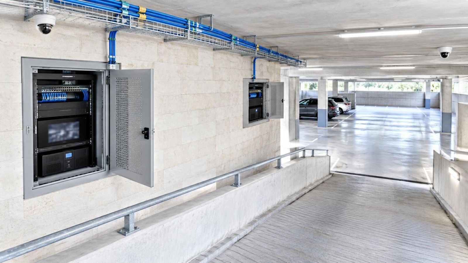
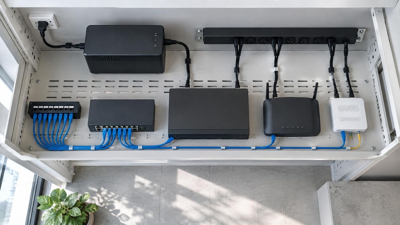
IP cameras may send video through an Ethernet switch to an NVR (network video recorder), while an internet router carries remote viewing and a wireless access point serves cameras or viewing devices without cable. In an Israeli home, reinforced walls around a mamad can change those paths significantly. A useful CCTV bandwidth calculation therefore answers one practical question: how much traffic crosses each local, wireless and internet link when recording, live viewing and playback happen together?
The total camera count is only the starting point. Network capacity is consumed where streams meet. A link carrying one camera has one load; the switch uplink carrying every recording stream may have a much larger one. The aim is not to produce a single impressive total. It is to identify each shared path and plan it with enough headroom.
Map Traffic Paths for a CCTV Bandwidth Calculation
Begin with a simple network drawing. Include every camera, switch, wireless bridge or access point, recorder, router and viewing station. Mark which device receives the recording stream. For most IP systems, that destination is an NVR or a server running VMS (video management software).
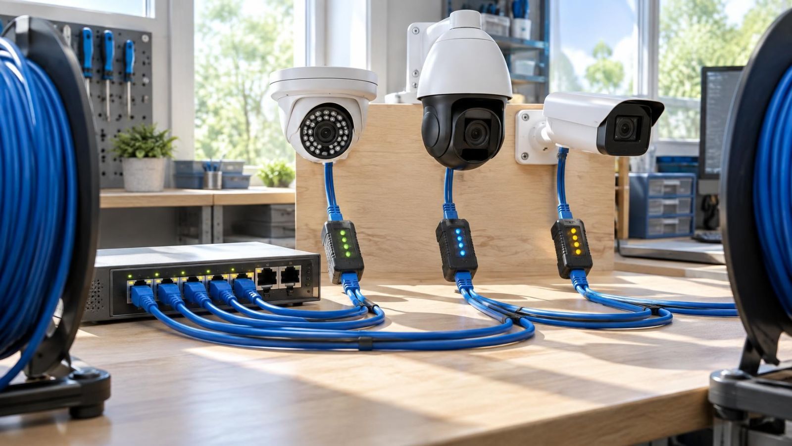
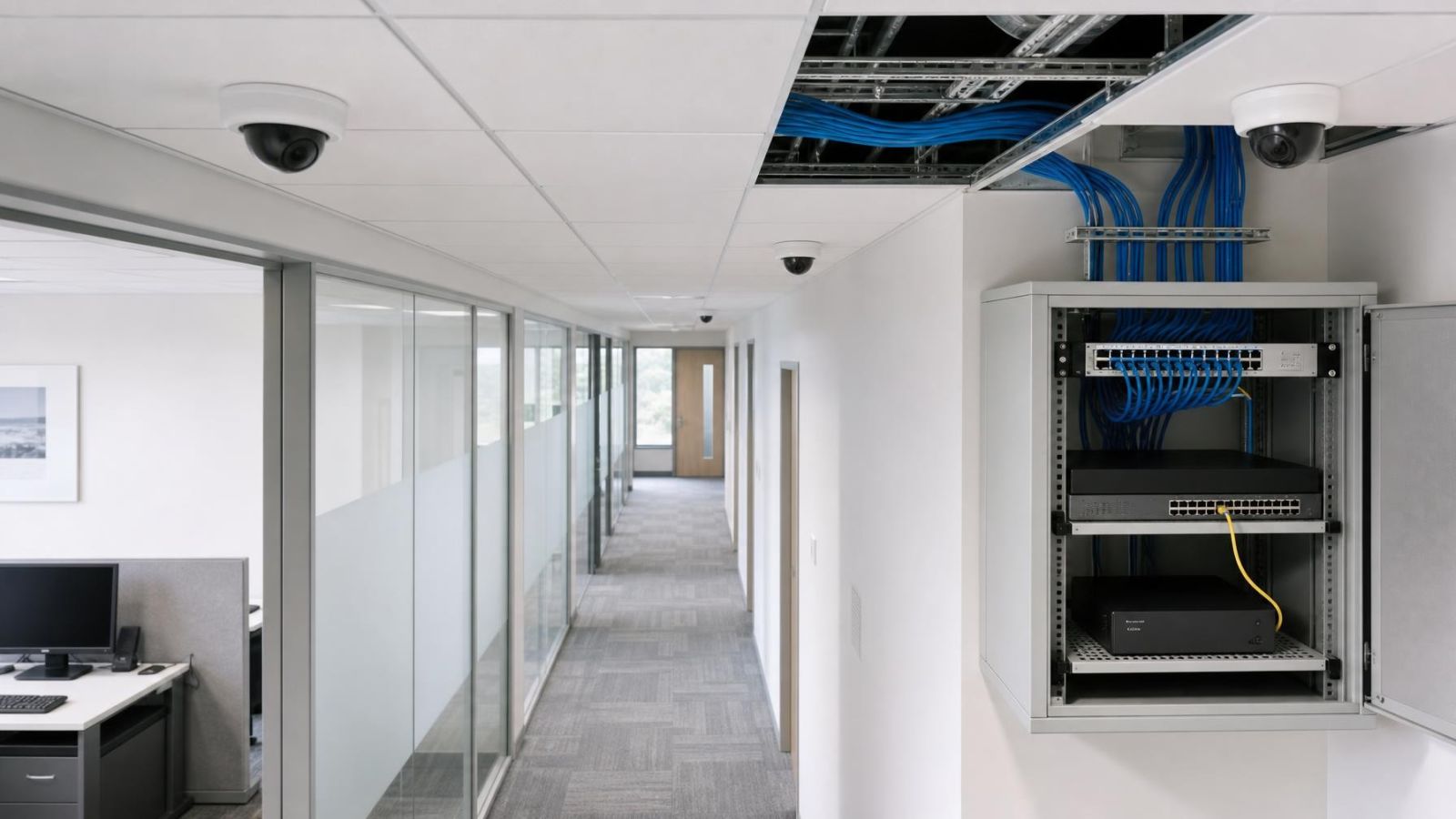
Next, draw the route from each camera to that destination. Cameras connected to the same PoE (power over Ethernet) switch may have independent access links but share the switch uplink. Cameras in a gate, garden or separate floor may share another cable, wireless bridge or intermediate switch. The IP camera bandwidth on each shared segment is the sum of the streams actually crossing it.
Do not assume that every stream follows the same route. A camera can supply a detailed main stream for recording and a lower-bandwidth secondary stream for routine live viewing. Depending on the system design, a viewing device may request video from the NVR, the VMS or the camera directly. Those choices place traffic on different links.
- Local recording normally loads the camera links, switch uplinks and recorder connection, but not the property’s internet upload path.
- Remote live viewing adds outbound traffic through the internet router. The remote site also needs a stable download path.
- Playback sends recorded video from the recorder to the viewing device. Local playback remains inside the property; remote playback crosses the internet connection.
- Direct camera viewing can create an additional stream from the camera. Recorder-based viewing can instead add traffic between the recorder and the client.
For a remotely managed property, note where remote access is actually terminated. A phone showing four small secondary streams creates a different load from a computer requesting several main streams. Both situations may be described as “viewing the cameras”, but they are not equivalent network events.
Calculate Bandwidth for Multiple Cameras
How do you calculate bandwidth for multiple cameras?
Use the configured bitrate of each active video stream as the planning input. Do not calculate from camera count alone. Bitrate depends on the pixel count per frame, frame rate, video compression settings, scene movement and image noise. Two cameras with apparently similar image settings can therefore produce different traffic.
For any shared link, use the basic relationship link video load = sum of all stream bitrates crossing that link. If every camera sends one recording stream through a switch uplink, add those recording bitrates there. If live view or playback also crosses the same uplink, add that traffic as well. Repeat the calculation separately for the recorder connection, router connection, wireless path and any link between floors or buildings.
The configured values must match the bitrate mode. Constant bitrate is intended to keep traffic around a defined rate, although actual behaviour still depends on the equipment and settings. Variable bitrate changes with scene complexity. It may be quiet when little is moving and rise sharply when foliage moves, headlights enter the frame or digital noise fills a dark image.
How much bandwidth does an IP camera need?
There is no reliable single allowance for every camera. Read the configured main-stream and secondary-stream bitrates, then confirm their behaviour under realistic conditions. The main stream usually dominates recording traffic. A secondary stream may be modest by comparison, but several simultaneous viewers can still make it relevant.
Leave network headroom above the expected peaks. Headroom gives ordinary business traffic, software updates, voice calls and temporary video peaks room to coexist without persistent contention. A design that only fits when every stream stays at its average has no useful margin when the scene becomes harder to compress.
Avoid double-counting. Watching an existing recording stream through the recorder does not necessarily make the camera send a second main stream. However, the recorder must send video to the client, so its own network connection carries additional outbound traffic. Check the actual stream path rather than relying on a generic diagram.
Find the Real Network Bottlenecks
A large total capacity figure can hide a narrow link. The practical task is to find the point where combined camera network bandwidth approaches the usable capacity or stability of one connection. Inspect each aggregation point separately.
| Network point | Traffic to include | Typical concern |
|---|---|---|
| Camera switch uplink | All streams leaving that switch | Shared capacity and uplink configuration |
| Recorder interface | Recording, live view and playback traffic | Combined inbound and outbound load |
| Router upload path | Remote live view and remote playback | Upload stability and other internet use |
| Wireless segment | Camera traffic and other wireless devices | Shared airtime, interference and coverage |
| Inter-floor or gate link | All traffic crossing the route | Single cable, bridge or intermediate switch |
The recorder connection deserves particular attention. It may receive every main recording stream while also serving live views and playback. A recorder with more than one network interface does not automatically divide those duties efficiently; the configured network routes determine which interface carries the traffic.
Can security cameras slow down the network?
Security cameras can affect other network activity when their traffic shares a constrained or unstable path. The security camera network load is most noticeable at shared uplinks, on wireless airtime and on the internet upload path during remote viewing. It is often less noticeable on individual wired camera connections because each access link carries only its own camera.
Wireless capacity needs different thinking from wired link capacity. Wireless cameras and other devices compete for airtime. Weak coverage can require retransmissions and slower connection rates, consuming more airtime for the same useful video. Reinforced mamad walls, multiple floors and an access point placed inside a communications cabinet can all make coverage less predictable.
In an apartment building, a camera at a shared entrance may cross common cabling or a wireless route before reaching a private recorder. In a private home, gate and garden cameras may converge on one outdoor link. In a street-frontage business, cameras, payment systems, staff devices and guest wireless access may all meet at the same switch or router. The bottleneck is determined by the path, not the property label.
Reduce Load Without Losing Useful Detail
How can camera network load be reduced?
Start with the purpose of each view. A camera covering a gate where faces must be recognisable needs different detail from a camera showing whether a storeroom door is open. Set resolution by the required pixel detail per frame, not by selecting the highest available setting everywhere.
Frame rate should follow scene activity. A quiet corridor generally changes less between frames than a busy entrance or a vehicle route. Reducing frame rate can lower bitrate, but going too far can remove useful moments from fast movement. Review recorded motion rather than judging the setting from a static live image.
Compression and bitrate mode also matter. More aggressive compression can reduce traffic and storage use, but may soften fine detail or create visible artefacts in movement. Variable bitrate can preserve quality across changing scenes, though it requires planning for peaks. Constant bitrate makes traffic more predictable but may spend capacity on simple scenes or constrain quality on complex ones.
Use the secondary stream for camera grids, mobile viewing and routine checks where full recorded detail is unnecessary. Keep the main stream available for recording and close inspection. Confirm that the VMS or recorder actually selects the intended stream for each viewing mode; creating a secondary stream does not help if every client continues to request the main stream.
Improve the scene before forcing the network to carry a difficult image. Strong Israeli sunlight can put a shaded entrance and bright street in the same frame. WDR (wide dynamic range), careful camera angle and controlled exposure can make that scene easier to use. At night, reflected IR, dirty covers and insufficient light can create noise. Moving trees, flags and road glare can keep variable bitrate unnecessarily high.
Decide Whether CCTV Needs a Dedicated Network
Should CCTV use a dedicated network?
A camera system benefits from deliberate traffic separation, but that does not always require completely separate switches and cabling. A managed switch can place cameras and the recorder on a dedicated VLAN (virtual local area network), control which devices can communicate and provide useful port-level traffic information. Physical separation goes further by giving the camera system its own switching path.
Logical separation improves organisation and visibility, but it does not create capacity. Two VLANs using the same constrained uplink still share that uplink. Physical separation can remove competition on selected links, yet remote access will normally still converge at the router and internet connection. The correct choice depends on the quality, spare capacity and manageability of the existing network.
| Approach | Main advantage | Important limitation |
|---|---|---|
| Shared unmanaged network | Simple topology | Limited traffic visibility and control |
| Managed network with VLAN | Separation, monitoring and flexible routing | Shared physical links still need headroom |
| Physically separate camera network | Dedicated local switching paths | Remote viewing still reaches shared internet infrastructure |
Property layout often decides more than theory. In a compact apartment, a managed switch and careful cabling may be sufficient. A private home with a gate, garden and several floors may justify separate access switches connected by stable wired uplinks. A street-frontage business may need clearer separation between cameras, staff systems and customer wireless access.
Treat the mamad as a coverage constraint, not as a reason to accept an unreliable camera link. Reinforced walls can weaken wireless service into or through the room. Where practical, route Ethernet around the difficult boundary, place the wireless access point on the side where coverage is needed, or use a wired camera connection. A dedicated wireless name does not solve weak radio coverage.
For apartment-building entrances and other shared areas, document which switch, cable route and internet connection carry the video. Coordination with the va’ad bayit may be needed for shared infrastructure decisions. From a technical perspective, unclear ownership often leads to unclear maintenance: nobody knows which device supplies power, which link is shared or where a fault should be tested.
Test the Design Before Finalising It
A calculation is a design tool, not a substitute for testing. Stream specifications describe intended settings. Real traffic changes with light, movement, viewing behaviour and network conditions. Test the complete path while the system is configured as it will actually operate.
- Confirm sustained recording from every camera. Watch switch uplinks and the recorder interface for errors, dropped links or prolonged saturation.
- Open the normal live-view layouts while recording continues. Use the same type of local and remote devices expected in routine operation.
- Run playback during live viewing. Test more than one recorded stream if operators are likely to review several cameras together.
- Create realistically busy scenes by walking through entrances, moving vehicles where appropriate, and testing foliage or glare that normally appears in the frame.
- Check remote access through the property’s usual internet connection. Observe the upload path while other expected internet activity continues.
- Verify wireless stability at the camera or bridge location, not merely beside the access point. Look for changing connection quality and retransmissions.
- Record the main-stream and secondary-stream settings, bitrate mode, frame rate, pixel resolution, switch ports, VLANs and route to the recorder.
If a test exposes a constraint, upgrade or reconfigure that part first. A saturated switch uplink calls for a different uplink design, not necessarily a new router. Weak wireless coverage calls for a better wired or radio path, not a higher internet package. Slow remote viewing may require reduced remote stream settings or more upload capacity, while leaving local recording untouched.
Retest after the change. The final documentation should show not only the devices but also the streams and shared links. That makes later expansion much easier: a new camera can be assessed against the path it will use rather than added blindly to a system-wide camera count.
The best design is not the one with the largest headline capacity. It is the one where recording, viewing and ordinary network use have clear routes, known limits and enough unused capacity to behave well when scenes become complex.
Key takeaways
- Camera traffic should be calculated per stream and combined separately at every shared network path.
- Network headroom should accommodate variable-bitrate peaks and ordinary traffic outside the camera system.
- Local recording loads property network links, while remote viewing also uses the internet upload path.
- Secondary streams and deliberate image settings can reduce viewing traffic without indiscriminately reducing recorded detail.
- Network upgrades should target the identified bottleneck rather than replace unrelated infrastructure.
Frequently asked questions
How to calculate CCTV bandwidth?
How to calculate bandwidth formula?
shared link load = sum of active stream bitrates crossing the link. Add main and secondary streams only when they are actually active on that route. Then include recorder-to-client live view or playback traffic as appropriate. The result should be compared with practical link capacity while retaining headroom for bitrate variation and unrelated network use.