On this page
A network camera may use twisted-pair cable passing through the same part of a building as a power cable, dedicated conduit and electrical panel. Before an installer reaches for a cable tester, the route itself must make sense. Good CCTV cable routing keeps the video link separated from likely noise sources, limits unavoidable crossings and leaves the cable accessible enough to test or replace. This article explains how to plan that route in an Israeli apartment, private home or small business.
Where Does Electrical Noise Come From?
Electrical noise is unwanted energy coupled into a camera link. It can affect an analogue video signal directly or disturb data and power conditions on a network connection. The result depends on the cable, the equipment and the route. A nearby power cable does not automatically mean a failed camera, but long shared paths create more exposure than properly separated routes.
Power distribution areas deserve particular attention. Electrical panels, heavy supply cables and crowded service spaces are poor places to gather spare camera cable or make an unnecessary detour. Motors and switching equipment can also create changing conditions. Typical examples include lift machinery, water pumps, gate motors, compressors and air-conditioning equipment.
What does camera cable interference look like?
The symptoms vary by system. Coaxial video may show moving bands, hum bars, distortion or an unstable picture. A network camera may disconnect, renegotiate its link, drop frames or restart if the same cable is also delivering unstable power. Similar symptoms can come from damaged cable, poor connectors, excessive link length or equipment faults, so appearance alone does not prove electrical interference.
Ground-potential differences are a separate concern in coaxial systems. When connected equipment sits at different electrical potentials, current can travel along an unintended path through the video connection. This ground-loop condition can create visible interference even when the coaxial cable itself is intact. Replacing the camera without examining the whole link often leaves the underlying condition unchanged.
Choose the Camera Cabling Method
Route planning starts with the installed equipment. A cable is not interchangeable simply because it fits through the available conduit. The camera interface, recorder or network switch, power arrangement, connector type and expected link all need to match.
| Cabling method | Typical use | Electrical-noise consideration |
|---|---|---|
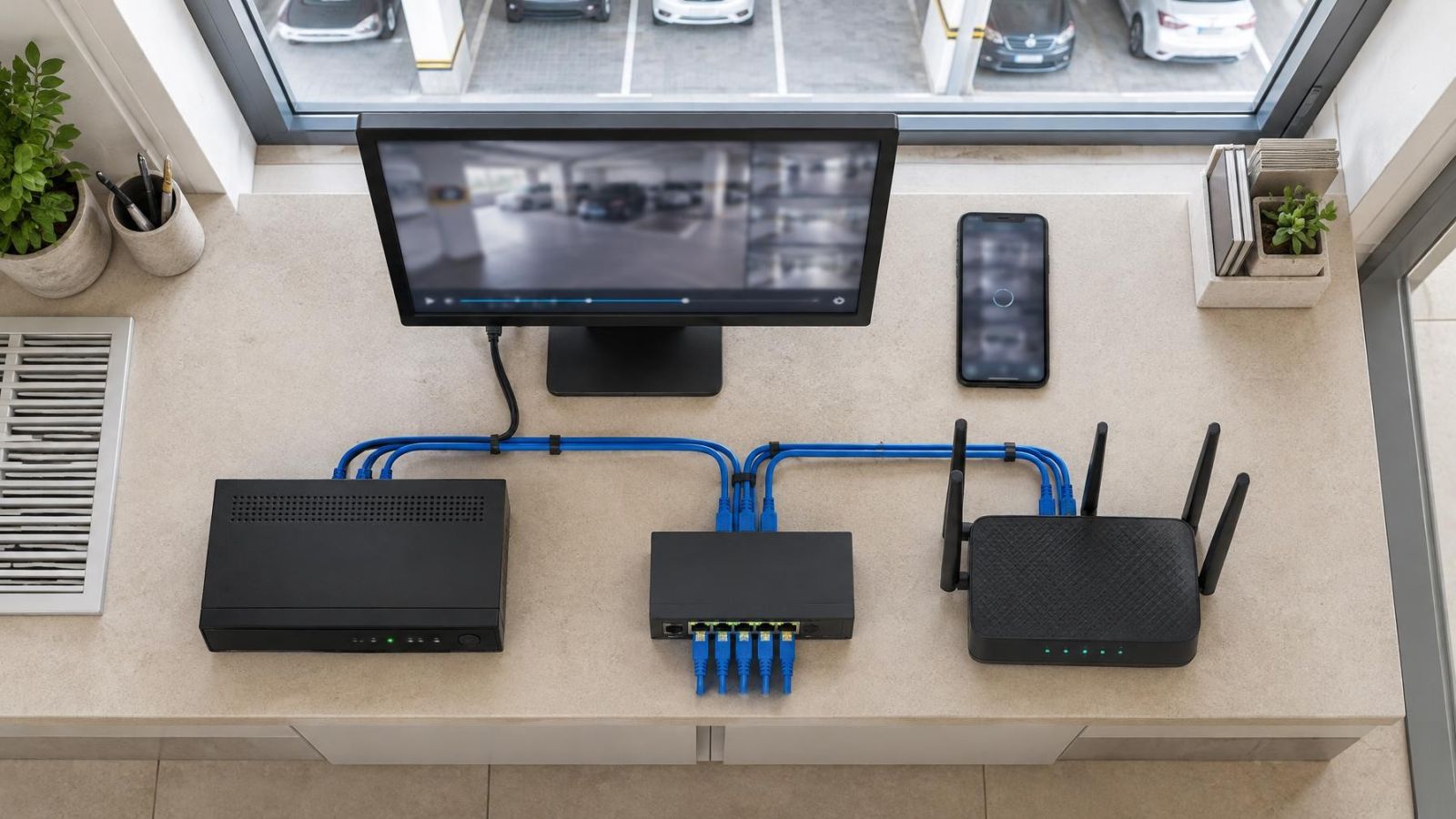
| Twisted-pair network cable | Network cameras connected to a switch or NVR | Twisting helps reject common interference, but routing and termination still matter |
| Coaxial cable | Analogue video connected to a DVR | Ground-potential differences and shield continuity require attention |
| Fibre optic cable | Links through electrically noisy areas or between separated network locations | The optical data path does not carry electromagnetic interference along the link |
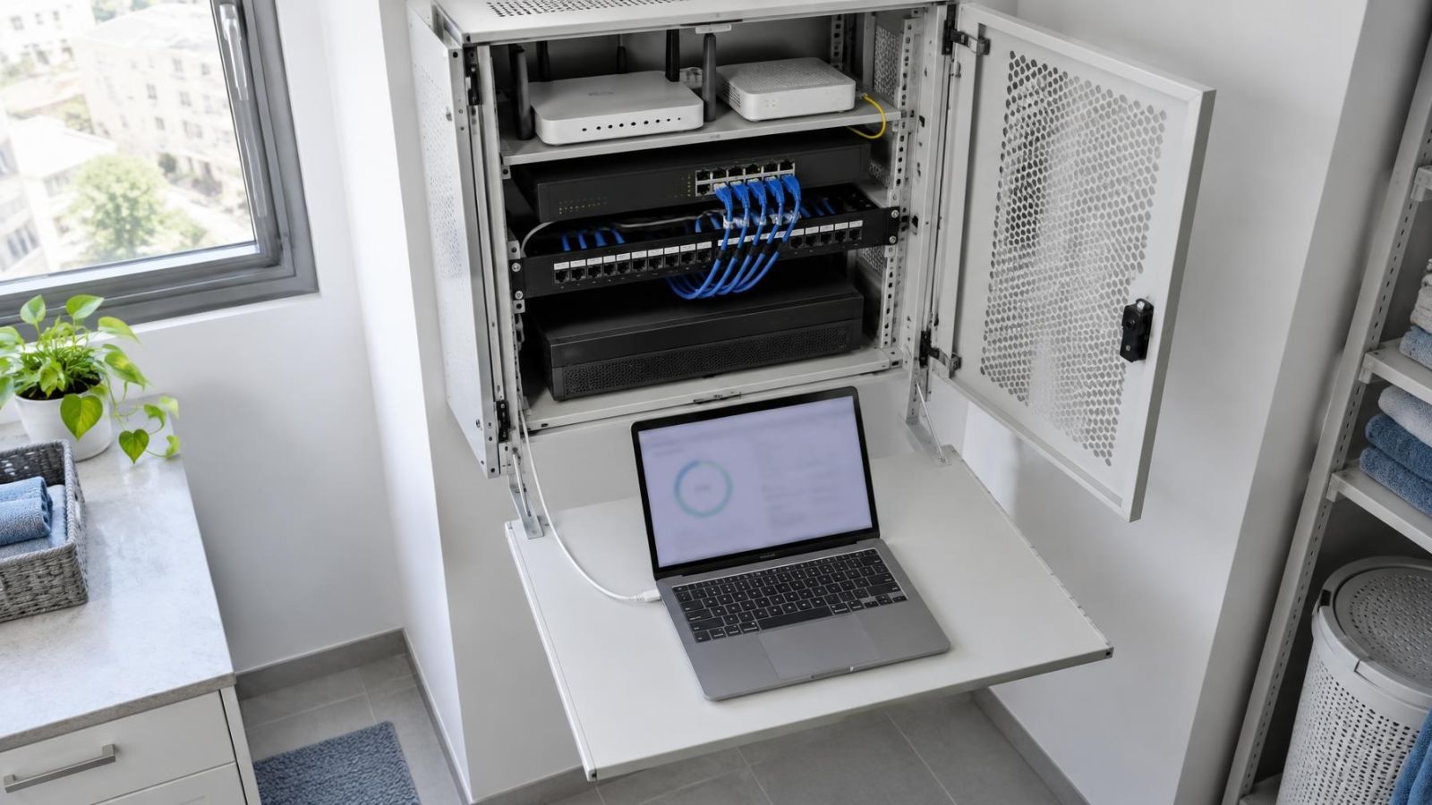
NVR means network video recorder. Network cameras usually connect over twisted-pair cable, sometimes using PoE (power over Ethernet) to carry data and operating power on the same link. PoE reduces the need for a separate local power supply, but it does not make route planning optional. Poor termination, cable damage, heat and electrical exposure can still affect the connection.
How should you choose a PoE cable route?
Choose a PoE cable route as both a data path and a power-delivery path. Keep it away from power distribution equipment and avoid unnecessary length, tight bends and inaccessible joints. Confirm that every part of the link is intended for the cable category and termination method being used. At the camera end, testing should cover network communication and delivered power rather than continuity alone.
Fibre is useful where separation from strong electrical activity is difficult or where an electrically isolated data link is preferable. It does not carry electromagnetic interference along the optical link. Cameras still need power, however, and the fibre termination equipment needs a suitable location. Fibre therefore changes the link design; it is not a direct replacement for every camera cable.
Plan CCTV Cable Routing Before Choosing the Path
Begin with separation, not with the shortest line between camera and recorder. A slightly longer serviceable route is often preferable to a direct path beside a main electrical feed. Mark the electrical panel, major power trunks, lift services, pumps, compressors, air-conditioning equipment and other switching loads before selecting the camera pathway.
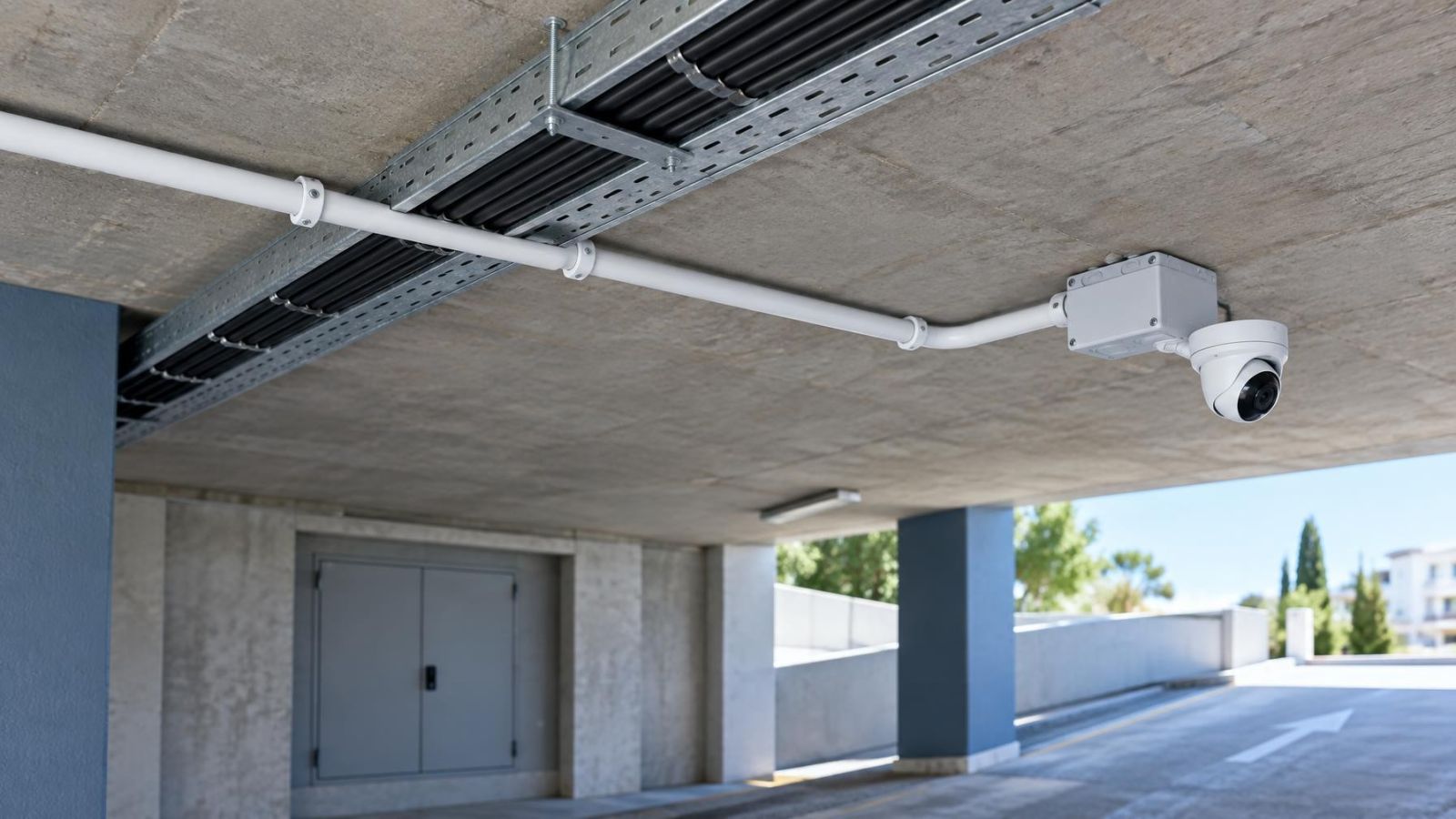
A dedicated conduit is the cleanest arrangement where practical. It creates predictable separation, protects the cable and makes later inspection or replacement easier. Shared cable channels should not be treated as harmless empty space. A channel may already contain power circuits, or may receive them later, leaving the camera cable trapped beside an avoidable noise source.
- Keep distance from distribution areas. Do not route closer to an electrical panel merely to save a small amount of cable.
- Avoid long parallel runs. Shared direction over a long distance creates more opportunity for coupling than a short crossing.
- Preserve access. Use paths where connectors, pull points and transitions can be inspected without opening finished surfaces unnecessarily.
- Plan replacement. Allow a cable to be withdrawn without disturbing power cabling or dismantling unrelated services.
- Protect bend radius. A route is not serviceable if tight corners damage the cable during pulling.
Can Camera Cables Cross Power Cables?
Yes, an unavoidable crossing can be planned as a brief, perpendicular crossing rather than a shared parallel run. The camera cable should approach the power cable, cross it at a right angle and regain separation immediately. This geometry limits the distance over which the two routes remain close.
What matters when routing Ethernet near power cables?
The important factors are proximity, shared distance, electrical load, cable construction and termination quality. Network cable electrical noise is more likely to become a concern when a cable follows a power route for an extended distance or passes repeatedly around high-load equipment. A brief crossing is different from placing both services side by side through a building.
Crowded space around an electrical panel is not a good place to improvise a crossing. If the camera route would have to weave among incoming and outgoing power cables, choose another path. Moving the camera cable to the opposite side of a corridor, ceiling void or service shaft can be more effective than adding accessories to a compromised route.
Treat separation as part of the cable design, not as a correction to attempt after the picture becomes unstable.
Use Shielding and Grounding Deliberately
Shielded cable can support a well-designed route, but it cannot compensate for poor routing or incorrect termination. A shield only performs as intended when the cable, connectors, patching hardware and connected equipment form a compatible system. An unconnected shield, an improvised connection or inconsistent components may add complexity without solving the original problem.
Grounding must also be considered as a complete arrangement. Connecting a shield casually at whatever metal point is nearby is not a design. The grounding approach must suit the equipment at both ends and the building's electrical arrangement. Where that arrangement is unclear, it should be reviewed by someone competent to assess the complete electrical system rather than only the camera connector.
Unshielded twisted-pair cable remains suitable for many camera links when it is correctly specified, terminated and routed through an appropriate pathway. Twisted pairs reject common noise by construction. Shielding becomes a considered design choice where the environment warrants it; it should not be the automatic answer to every nearby cable.
For coaxial video, the outer conductor is part of the signal path as well as the cable's screening arrangement. Poor connectors, damaged braid and ground-potential differences can all produce visible symptoms. Diagnosis should therefore include both cable condition and the way equipment at each end is powered.
Account for Israeli Building Conditions
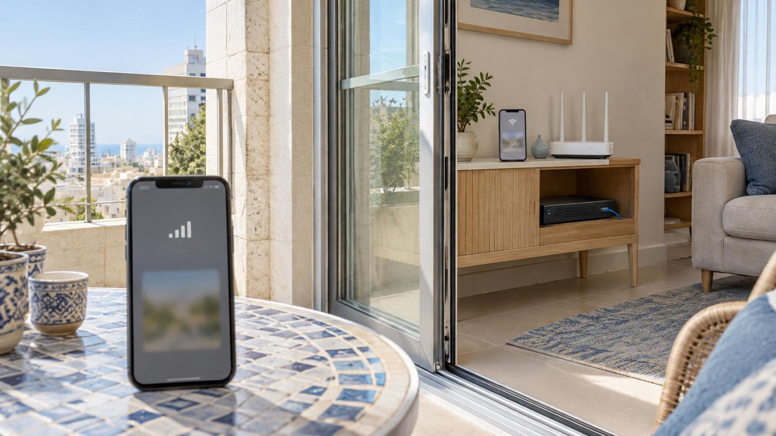
Existing Israeli apartments often have crowded conduits and limited service space. The apparent direct route may already contain electrical wiring or may be too tight to pull a network cable without damage. Check the full pathway, including bends and boxes, rather than assuming that an opening at each end proves the conduit is usable.
Apartment buildings also contain shared entrances, stairwells, parking areas and service shafts. A camera route through these areas may depend on access and coordination with the va'ad bayit, the building committee. Agreeing where the cable will pass and where equipment can be reached for maintenance avoids creating an inaccessible section between the private apartment and shared infrastructure.
A mamad, the reinforced safe room found in many Israeli homes, can limit practical penetration routes. Its walls should be treated as a fixed planning constraint. Use existing suitable openings where available and decide early whether the recorder, switch or camera cable needs to cross the room boundary. Discovering the constraint after finishing the internal route can force an exposed detour.
Outdoor transitions need their own route assessment. Strong sunlight, dust and coastal humidity can affect exposed jackets, boxes and connectors. The cable should move between indoor and outdoor conditions through a protected, inspectable transition, with suitable support and without creating a path for water to run into equipment.
Street-front businesses present a different problem. Signage, air conditioning, refrigeration, lighting and distribution equipment may occupy the same ceiling or rear service area. Map these services before deciding where the camera cables converge. A neat bundle is not good workmanship if it ties data cabling to a changing group of power circuits.
Test the Finished Route Under Load
Testing should begin before walls and ceilings are closed. First inspect the entire visible route. Look for crushed cable, sharp bends, unsupported sections, exposed transitions and places where separation disappeared during installation. Then use a cable tester appropriate to the link to check continuity, pair order and termination quality.
- Confirm the route and inspect every accessible transition, pull point and termination.
- Test cable continuity and termination before connecting the camera equipment.
- Connect the camera and confirm stable communication with the NVR, DVR or VMS (video management software), as applicable.
- For PoE, verify power delivery at the camera end while the camera is operating.
- Run nearby lifts, pumps, air-conditioning equipment, gates or other relevant electrical loads.
- Watch the live stream and recording for bands, distortion, dropouts, restarts or link changes.
- Change the route or correct the termination before finished surfaces make access difficult.
A camera that works while the building is quiet has not completed the most useful test. Nearby electrical equipment should be operating so the route experiences realistic conditions. For an analogue system, inspect the image carefully for moving bands and instability. For a network system, check sustained stream behaviour rather than relying on a single successful connection.
Testing also needs to separate route faults from equipment faults. If a symptom appears, compare terminations, inspect the cable and, where practical, test through a temporary cable laid on a clearly separated path. A stable temporary path does not by itself identify the exact defect, but it helps determine whether the installed route deserves closer examination.
Key takeaways
- Route separation is more dependable than adding corrective accessories after installation.
- A dedicated pathway improves cable separation, inspection and future replacement.
- A brief perpendicular crossing exposes a camera cable to less shared distance than a parallel run.
- Shielding works only when the cable, connectors, equipment and grounding arrangement are compatible.
- Testing while nearby electrical equipment operates can reveal problems that an idle-site test misses.